9-7
9-1 Connection Examples
9
Appendix
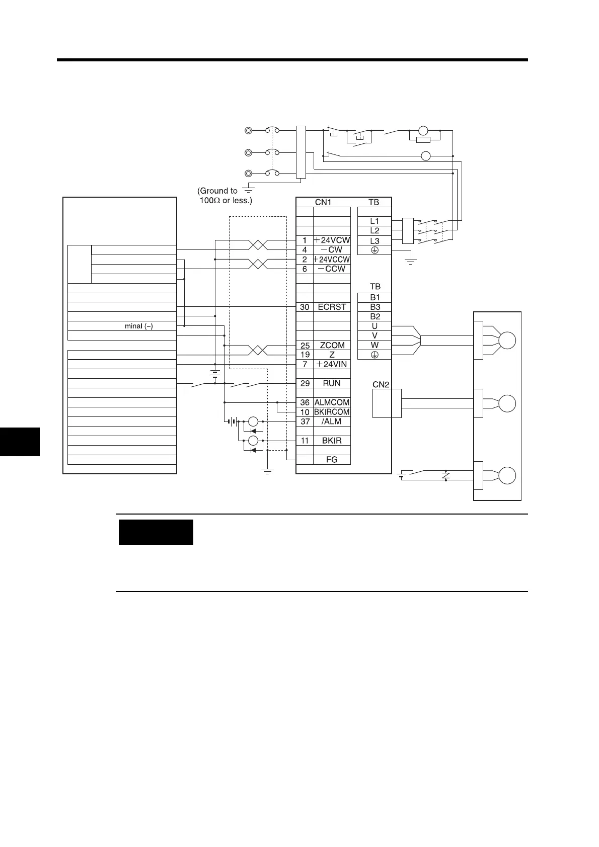
Connection Example 7: Connecting to SYSMAC CP1H-X@@DT-D/
CP1L-@@@DT-D
• Incorrect signal wiring can cause damage to Units and the Servo Drive.
• Leave unused signal lines open and do not wire them.
• Do not share the power supply for brakes (24 VDC) with the 24-VDC power
supply for controls.
• The diode recommended for surge absorption is the RU 2 manufactured
by Sanken Electric or the equivalent.
S
X1
XB
R
T
NFB
X1
MC1
M
E
B
XB
MC2
24 VDC
24 VDC
24 VDC
Shell
Reactor
CP1H-X40DT-D R88-GT@
Noise filter
3-phase 200 to 240 VAC 50/60 Hz
R88M-G@
Output terminal block
CW0 (CIO 0100.00)
COM (for CIO 0100.00)
CCW0 (CIO 0100.01)
COM (for CIO 0100.01)
Origin search 0 (CIO 0101.02)
24-VDC input terminal (+)
COM (CIO 0101.00 to 0101.03)
Input terminal block
24-VDC input ter
Pulse 0 origin input signal (CIO 0001.03)
COM (CIO 0000)
Pulse 0 origin proximity input signal (CIO 0000.01)
Servomotor
Power Cable
R88A-CAG@
Red
White
Blue
Green/
Yellow
Encoder Cable
R88A-CRG@
Brake Cable
R88A-CAGA@B
R88A-CAGE@B
Pulse
output 0
Servo error display
X1
PL
ONOFF
X
1MC
Main circuit power supply
Main circuit contactor
1MC
surge suppressor
Precautions
for Correct Use
 Loading...


