7-26
7-5 Manual Tuning
7
Adjustment Functions
Gain Switching Function
With manual tuning, Gain 1 and Gain 2 can be set manually. The gain can be switched according
to the operation.
Switching from Gain 1 to Gain 2 can be used for the following applications.
• To increase responsiveness by increasing the gain during operation.
• To increase servo lock rigidity by increasing the gain when operation is stopped.
• To switch to an optimal gain according to the operating mode.
• To reduce the gain to suppress vibration when operation is stopped.
Application Example
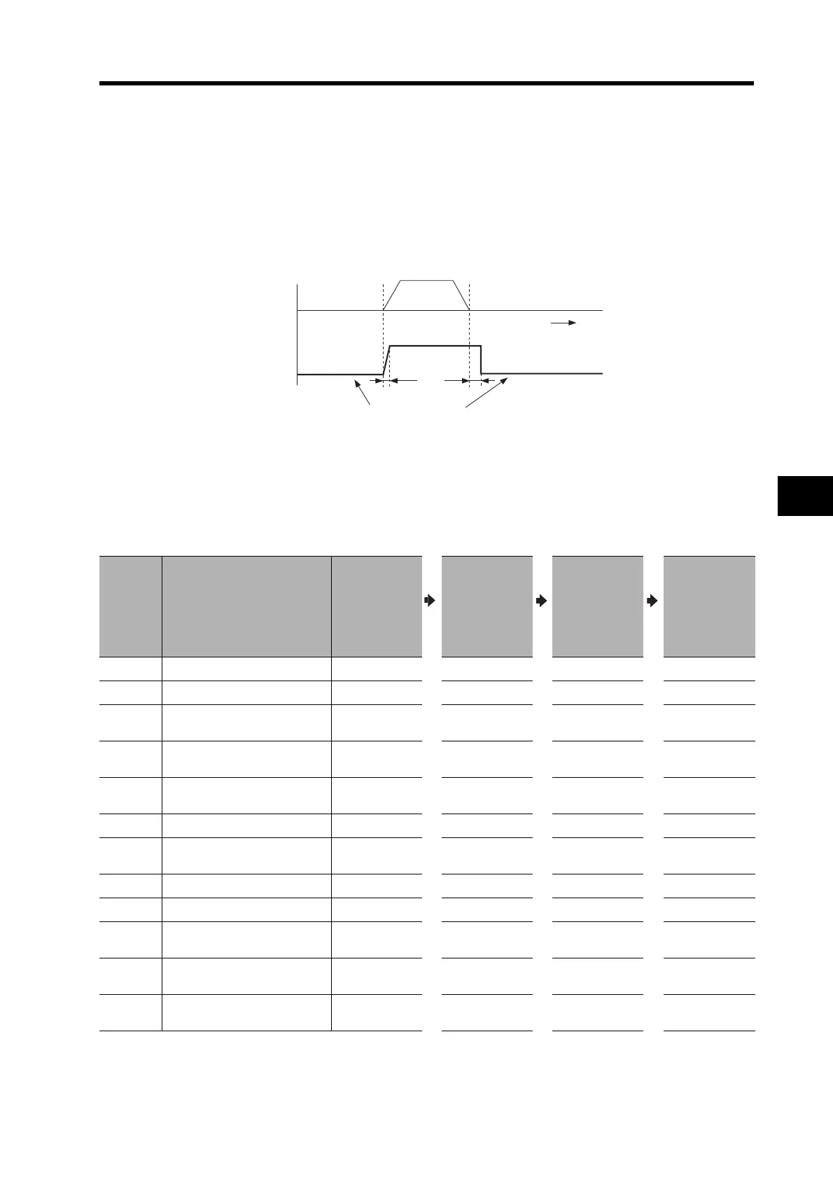
The example is for a case where noise is a problem when the Servomotor is stopped (servo lock),
and the noise is reduced by switching to a lower gain setting after the Servomotor has stopped.
Refer to Normal Mode Autotuning on page 7-16 for information on making adjustments.
Parameter
No.
Parameter name
Perform
manual tuning
without gain
switching.
Set Gain 2
(Pn18 to Pn1C)
to the same
values as Gain
1 (Pn10 to
Pn14).
Set gain
switching
conditions
(Pn30 to Pn35).
Adjust Pn11
and Pn14
(for Gain 1)
when stopped.
Pn10 Position Loop Gain 60
Pn11 Speed Loop Gain 50 30
Pn12
Speed Loop Integration Time
Constant
16
Pn13
Speed Feedback Filter Time
Constant
0
Pn14
Torque Command Filter Time
Constant
50 85
Pn15 Feed-forward Amount 300
Pn16
Feed-forward Command
Filter
50
Pn18 Position Loop Gain 2 60
Pn19 Speed Loop Gain 2 50
Pn1A
Speed Loop Integration Time
Constant 2
16
Pn1B
Speed Feedback Filter Time
Constant 2
0
Pn1C
Torque Command Filter Time
Constant 2
60
Operation
Status
1 ms 2 ms
Drive
Time
Gain
Command
speed
Stop
(Servo lock)
Low gain
(Gain 1)
Stop
(Servo lock)
Low gain
(Gain 1)
High gain
(Gain 2)
Vibration is suppressed
by lowering the gain.

 Loading...

