7-27
7-5 Manual Tuning
7
Adjustment Functions
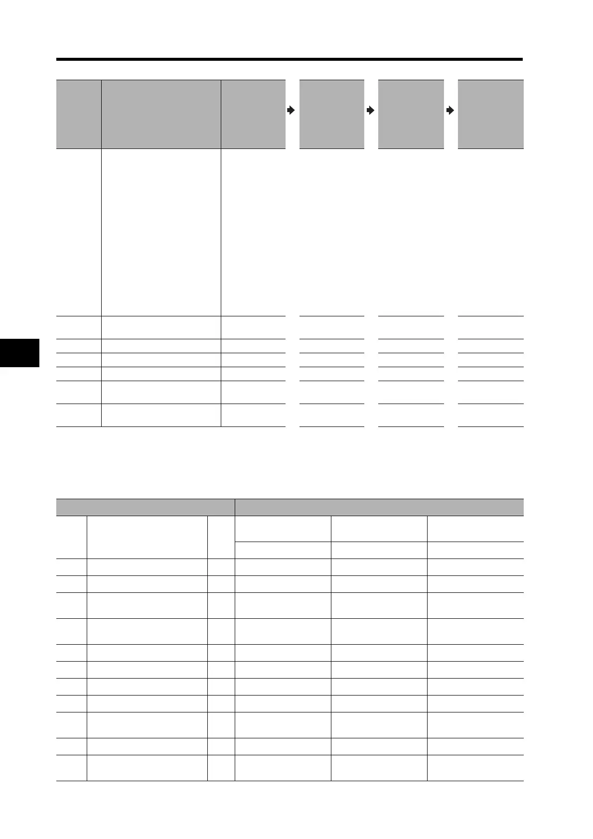
Setting Gain Switching Conditions
Position Control Mode (: Relevant parameter enabled, ---: Disabled)
Parameter
No.
Name
Perform
manual tuning
without gain
switching.
Set Gain 2
(Pn18 to Pn1C)
to the same
values as Gain
1 (Pn10 to
Pn14).
Set gain
switching
conditions
(Pn30 to Pn35).
Adjust Pn11
and Pn14
(for Gain 1)
when stopped.
Pn20 Inertia Ratio
• Enter the
value for
load calcu-
lation if
already
known.
• Perform
normal
mode auto-
tuning and
measure
the inertia
ratio.
• The default
is 300.
Pn30
Gain Switching Input
Operating Mode Selection
01
Pn31 Control Gain Switch 1 Setting 7
Pn32 Gain Switch 1 Time 30
Pn33 Gain Switch 1 Level Setting 0
Pn34
Gain Switch 1 Hysteresis
Setting
0
Pn35
Position Loop Gain Switching
Time
0
Gain Switch Setting Setting parameters for position control mode
Pn31
Conditions for switching to
gain 2
Fig-
ure
Gain Switch Time
*1
Gain Switch Level
Setting
Gain Switch Hysteresis
Setting
*2
Pn32 Pn33 Pn34
0 Always gain 1 --- --- --- ---
1 Always gain 2 --- --- --- ---
2
Switching using Gain Switch
Input (GSEL)
--- --- --- ---
3
Amount of change in torque
command
---
*3
(0.05%/166 μs)
*3
(0.05%/166 μs)
4 Always gain 1 A --- --- ---
5 Command speed --- (r/min) (r/min)
6 Amount of position deviation C
*4
(pulse)
*4
(pulse)
7 Command pulses received D --- ---
8
Positioning Completed
Output
F --- ---
9 Actual Servomotor speed C (r/min) (r/min)
10
Combination of command
pulse input and speed
G (r/min)
*6
(r/min)
*6

 Loading...

