5-80
5-16 User Parameters
5
Operating Functions
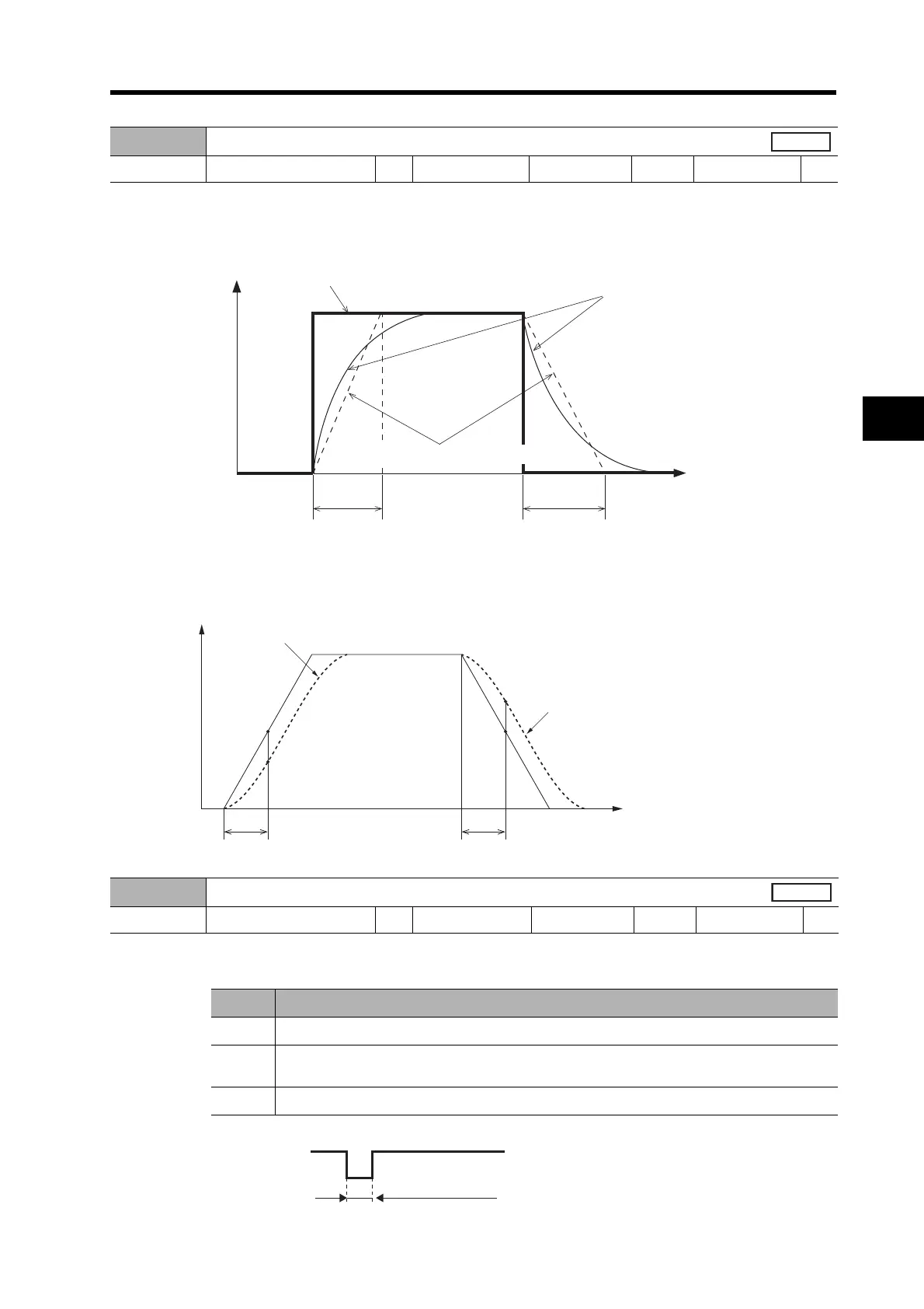
• Use this parameter to select the FIR filter time constant used for the command pulses (FIR: Finite
impulse response).
• The higher the setting, the smoother the command pulses.
• If the setting is 0, the control cycle will be (0 + 1)
× 166 = 166 μs.
If the setting is 1, the control cycle will be (1 + 1)
× 166 = 332 μs.
Likewise, if the setting is 31, the control cycle will be (31 + 1)
× 166 = 5,312 μs.
Explanation of Settings
• If Pn4E is set to 0, the minimum time width of the ECRST signal will be as follows:
Pn4D
Smoothing Filter Setting
Setting range 0 to 31 Unit --- Default setting 0
Power OFF→ON
Yes
Pn4E
Deviation Counter Reset Condition Setting
Setting range 0 to 2 Unit --- Default setting 1
Power OFF→ON
---
Setting Explanation
0 Clears the deviation counter when the signal is closed for 100 μs or longer.
1
Clears the deviation counter on the falling edge of the signal (open and then closed for
100
μs or longer).
2 Disabled
Command
Input position command
Position command after
smoothing filter processing
Position command after FIR filter processing
tf = (Pn4E + 1) × Control cycle
Time
t
f
t
f
t
f
t
f
Response with position loop gain
Response with position
loop gain
ECRST (pin 30)
100 μs min.

 Loading...

