7-25
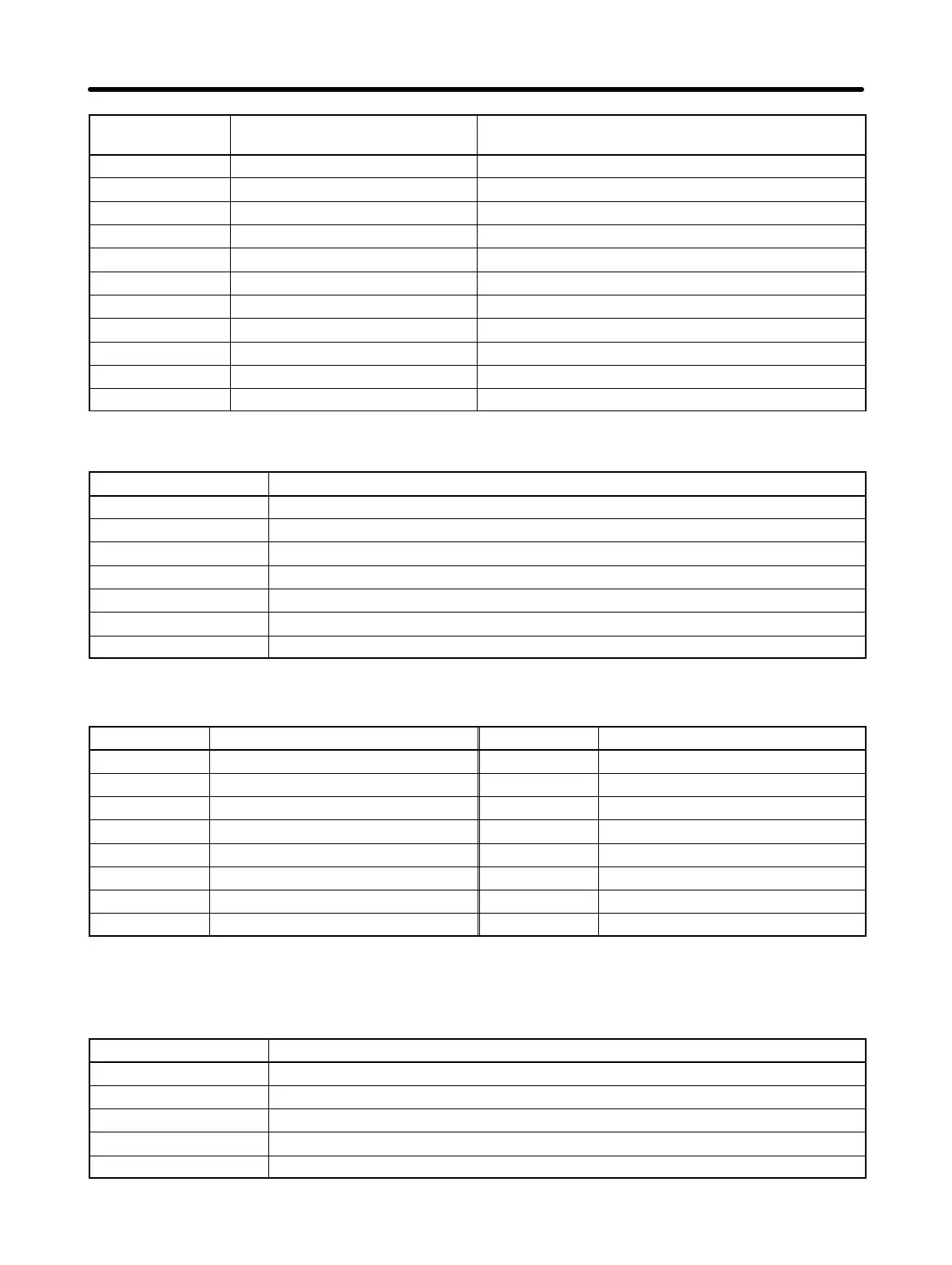
Register No.
(Hex)
DescriptionFunction
0027 Output current Read based on 1 A as 10.
0028 Output voltage Read based on 1 V as 1.
0029 to 002A Not used. ---
002B Input terminal status Refer to the following corresponding table.
002C Inverter status 1 Refer to the following corresponding table.
002D Output terminal status Refer to the following corresponding table.
002E to 0030 Not used. ---
0031 Main circuit DC voltage Read based on 1 V as 1.
0032 to 003C Not used. ---
003D Communications error Refer to the following corresponding table.
003E to 00FF Not used. ---
D Status Signal (Register 0020 Hex)
Bit No. Function
0 During RUN (1: During RUN)
1 Forward/reverse operation (1: Reverse operation)
2 Inverter ready (1: Ready)
3 Fault (1: Fault)
4 Data setting error (1: Error)
5 Multi-function output (1: ON)
6 to 15 Not used.
D Fault Status (Register 0021 Hex)
Bit No. Function Bit No. Function
0 OC 8
Fj
1 OV 9 OL1
2 OL2 10 OL3
3 OH 11 Not used.
4 Not used. 12 UV1
5 Not used. 13 GF
6 Not used. 14 CE
7
EFj, STP
15 Not used.
Note When a fault results, the corresponding bit will be set to 1.
D Data Link Status (Register 0022 Hex)
Bit No. Function
0 Data writing (1: Writing)
1 to 2 Not used.
3 Upper and lower limit error (1: Error): Outside set range
4
Verify error (1: Error): Same as OPEj.
5 to 15 Not used.
Communications Chapter 7