7-41
put) of the Inverter, and monitors the Inverter status.
Three Inverters with Slave addresses from 01 to 03 are installed for communications.
D Checking the Register Numbers
• In the above example, the following three registers are required.
Control Input: Register 0001 Hex for RUN command
Frequency Reference: Register 0002 Hex
Control Output: Register 002C Hex for Inverter status
D Memory Allocations
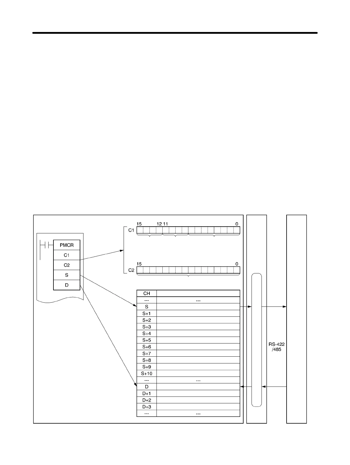
• The PMCR instruction sends each Slave the data in consecutive words specified by the operand and
beginning with the first word (S), and writes in the memory area beginning with the first word (D) the
data received.
• The following memory allocations are made in the above example.
SYSMAC CS/CJ-series Programmable Controllers
Communications
Board/Unit
3G3JV
Control data
Serial port
Port 1: 1 Hex
Port 2: 2 Hex
Sequence No.
0000 to 03E7 Hex (000 to 999)
Data
No. of data items sent in accordance with PMCR
instruction (000B)
No. of Slaves (0003)
First Slave address (0001)
RUN command to Slave 1
Frequency reference to Slave 1
Second Slave address (0002)
RUN command to Slave 2
Frequency reference to Slave 2
Third Slave address (0003)
RUN command to Slave 3
Frequency reference to Slave 3
No. of data items received in accordance with
PMCR instruction (0003)
Slave 1 Inverter status
Slave 2 Inverter status
Slave 3 Inverter status
Protocol macro function
C1
Communications
port
0 to 7 Hex
Communications Board/Unit
unit number specification
Inner board: E1 Hex
CPU Bus Unit: Unit number
+ 10 Hex
Communications Chapter 7