10-3
Parame-
ter No.
(Register
No.
(Hex))
Refer-
ence
page
Changes
during op-
eration
Default
setting
Unit of
setting
Setting
range
DescriptionName
n06
(0106)
STOP/RE-
SET Key
function
selection
Used to select the stop method in remote
mode with n02 for operation mode selection
set to 1.
0: STOP/RESET Key of the Digital Operator
enabled.
1: STOP/RESET Key of the Digital Operator
disabled.
0, 1 1 0 No 5-7
n07
(0107)
Frequency
selection
in local
mode
Used to set the input method for the frequency
reference in local mode.
0: The FREQ adjuster of the Digital Operator
enabled.
1: Key sequences on the Digital Operator
enabled.
0, 1 1 0 No 5-8
n08
(0108)
Key se-
quential
frequency
setting
Used to enable the Enter Key for setting the
frequency reference with the Increment and
Decrement Keys.
0: The value is entered with the Enter Key
pressed.
1: The value is enabled when the value is
input.
0, 1 1 0 No 5-12
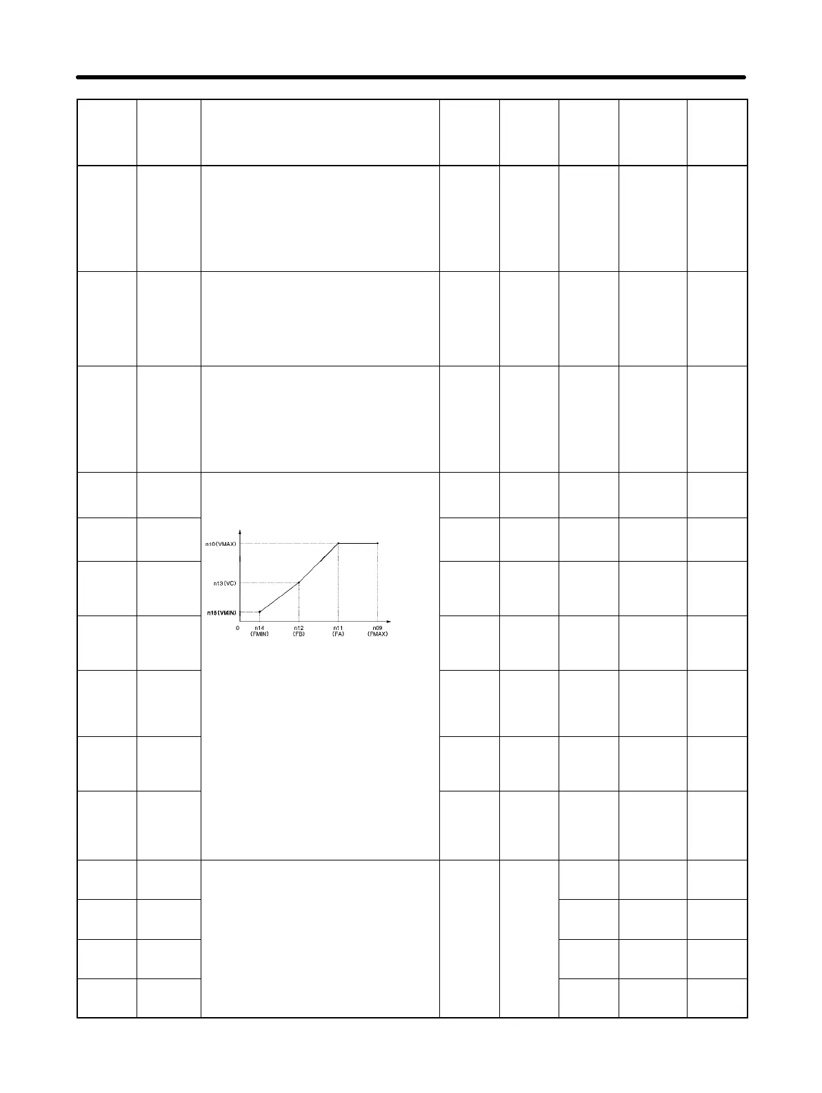
n09
(0109)
Maximum
frequency
(FMAX)
Used to set the V/f pattern as the basic char-
acteristic of the Inverter with output voltage
per frequency set.
50.0 to
400
0.1 Hz
(see note
1)
60.0 No 5-4
n10
(010A)
Maximum
voltage
(VMAX)
Output
voltage
1 to 255
(see note
2)
1 V 200 (see
note 2)
No 5-4
n11
(010B)
Maximum
voltage
frequency
(FA)
0.2 to 400 0.1 Hz
(see note
1)
60.0 No 5-4
n12
(010C)
Middle
output fre-
quency
(FB)
Frequency
(Hz)
Note Set the parameters so that the follow-
ing condition will be satisfied
0.1 to 399 0.1 Hz
(see note
1)
1.5 No 5-4
n13
(010D)
Middle
output fre-
quency
voltage
(VC)
ng con
on w
e sa
s
e
.
n14 x n12 < n11 x n09
Note The value set in n13 will be ignored if
parameters n14 and n12 are the same
1 to 255
(see note
2)
1 V 12 (see
note 2)
No 5-4
n14
(010E)
Minimum
output fre-
quency
(FMIN)
in value.
0.1 to
10.0
0.1 Hz 1.5 No 5-4
n15
(010F)
Minimum
output fre-
quency
voltage
(VMIN)
1 to 50
(see note
2)
1 V 12.0 (see
note 2)
No 5-4
n16
(0110)
Accelera-
tion time 1
Acceleration time: The time required to go
from 0% to 100% of the maximum frequency.
Deceleration time: The time required to go
0.0 to 999 0.1 s
10.0 Yes 5-14
n17
(0111)
Decelera-
tion time 1
ece
erat
on t
me:
e t
me requ
re
to go
from 100% to 0% of the maximum frequency.
Note The actual acceleration or deceleration
time is obtained from the following for
10.0 Yes 5-14
n18
(0112)
Accelera-
tion time 2
time is obtained from the following for-
mula.
Acceleration/Deceleration time = (Ac-
10.0 Yes 5-14
n19
(0113)
Decelera-
tion time 2
celeration/Deceleration time set value)
× (Frequency reference value) ÷ (Max.
frequency)
10.0 Yes 5-14
List of Parameters Chapter 10