Pin No.
Circuit Signal name
Output specifications
Axis
1 / 3
Axis
2 / 4
Item Description
B7 B16
COM ON state max.
voltage drop
1.0 V
(Note 1) The deviation counter clear signal is output when the power supply is turned ON for about 1 ms. When
the home return is complete, the signal is output for about 1 ms or 10 ms. The time can be specified
using the "Parameter".
Power supply terminal (common)
Pin No.
Circuit Signal name
Power supply specifications
Item Description
A20
External power supply
input:
24 V DC (+)
Supplied power
supply range
21.4 to 26.4 V DC
B20
External power supply
input:
24 V DC (-)
Consumption current 90 mA or less
(Note 1) The external power supply input terminals between two connectors are connected internally.
Input terminals (common)
Pin No.
Circuit Signal name
Input specifications
Axis
1 / 3
Axis
2 / 4
Item Description
A3 A12
Home input
24 V DC (+)
(Z24)
Operating voltage
range
21.6 to 26.4 V DC
Min. ON voltage /
current
19.2 V DC / 5.5 mA
Max. OFF voltage/
current
2 V DC / 2 mA
Input impedance Approx. 3.9 kΩ
Pulse width 100 μs or more
A4 A13
Home input
5 V DC (+)
(Z5)
Operating voltage
range
3.5 to 5.25 V DC
(5 V DC, Line driver
specifications)
Min. ON voltage /
current
3 V DC / 4 mA
Max. OFF voltage/
current
1 V DC / 0.5 mA
Input impedance Approx. 560 Ω
Pulse width 100 μs or more
B3 B12 Home input (-) - -
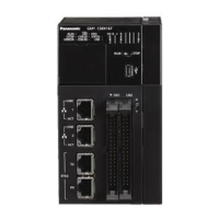
16.2 Performance Specifications of the Pulse Output Unit
WUME-GM1PG-01 16-5

 Loading...