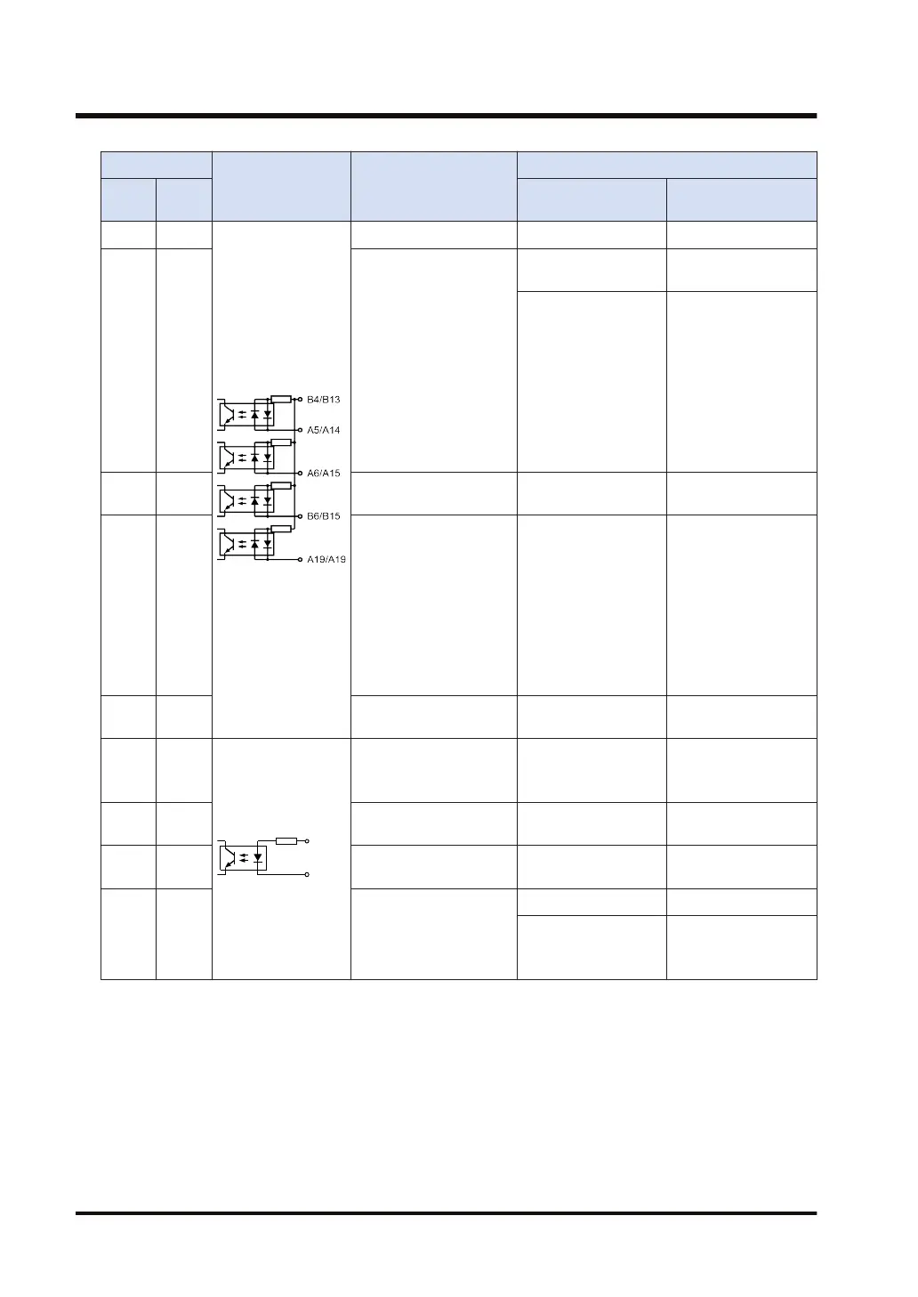
Pin No.
Circuit Signal name
Input specifications
Axis
1 / 3
Axis
2 / 4
Item Description
B4 B13 COM - -
A5 A14 Near home input (DOG)
Operating voltage
range
21.6 to 26.4 V DC
Min. ON voltage /
current
Near home input
(DOG)
19.2 V DC / 5.0 mA
Over limit input (+)
Over limit input (-)
Positioning control
start input (Timing
input)
19.2 V DC / 2.6 mA
A6 A15 Over limit input (+)
Max. OFF voltage/
current
2 V DC / 1.5 mA
B6 B15 Over limit input (-) Input impedance
Near home input
(DOG)
Approx. 3.6 kΩ
Over limit input (+)
Over limit input (-)
Positioning control
start input (Timing
input)
Approx. 6.8 kΩ
A19 B19
Positioning control start
input (Timing input)
Pulse width 500 μs or more
A8 A17
Pulse input A (+)
Operating voltage
range
3.5 to 5.25 V DC
(5 V DC, Line driver
specifications)
B8 B17 Pulse input A (-)
Min. ON voltage /
current
3 V DC / 3.2 mA
A9 A18 Pulse input B (+)
Max. OFF voltage/
current
1 V DC / 0.5 mA
B9 B18 Pulse input B (-)
Input impedance Approx. 560 Ω
Pulse width
0.5 μs or more
(Max. 1 MHz each
phase)
16.2 Performance Specifications of the Pulse Output Unit
16-6 WUME-GM1PG-01

 Loading...