EasyManuals Logo

Parker P Series User Manual

Parker P Series
316 pages
To Next Page IconTo Next Page
To Previous Page IconTo Previous Page
Page #100 background imageLoading...
Page #100 background image
Parker Hannifin
P Series User Guide 98
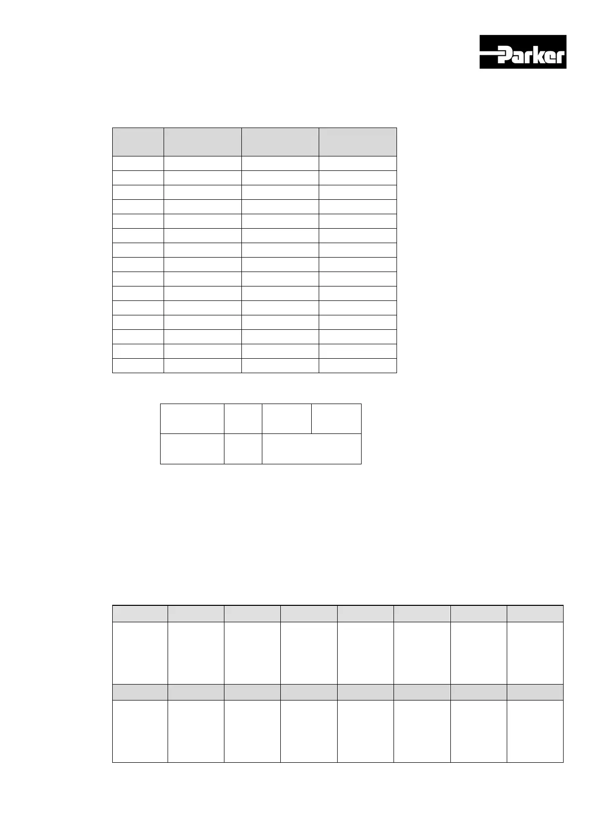
You can set the functions of digital input signal of I/O connector and input signal level.
Choose the signals to allocate with bit 7~0, and set the signal level at bit 15.
Set
Value
Allocated
Signal
Set
Value
Allocated
Signal
0x00
Not allocated
0x11
PAUSE
0x01
POT
0x12
REGT
0x02
NOT
0x13
HSTART
0x03
HOME
0x14
ISEL0
0x04
STOP
0x15
ISEL1
0x05
PCON
0x16
ISEL2
0x06
GAIN2
0x17
ISEL3
0x07
P_CL
0x18
ISEL4
0x08
N_CL
0x19
ISEL5
0x09
PROBE1
0x1A
ABSRQ
0x0A
PROBE2
0x1B
JSTART
0x0B
EMG
0x1C
JDIR
0x0C
A_RST
0x1D
PCLR
0x0F
SV_ON
0x1E
AOVR
0x10
START
Example) When the set value is 0x0006.
0 0 0 6
CONTACT A GAIN2Allocation
Contact A: Base status is 0(Low). Activates when 1(High) is input.(Active High)
Contact B: Base status is 1(High). Activates when 0(Low) is input (Active Low)
Example of Input Signal Allocation
The table below shows an example of allocating input signals. Please note the set values
of 0x2200~0x220F.
DI1
DI2
DI3
DI4
DI 5
DI 6
DI 7
DI 8
SV_ON
(CONTA
CT A)
POT
(CONTAC
T A)
NOT
(CONTAC
T A)
A-RST
(CONTAC
T A)
START
(CONTAC
T A)
STOP
(CONTAC
T A)
REGT
(CONTAC
T A)
EMG
(CONTAC
T A)
DI 9
DI 10
DI 11
DI 12
DI 13
DI 14
DI 15
DI 16
HOME
(CONTA
CT B)
HSTART
(CONTAC
T B)
ISEL0
(CONTAC
T A)
ISEL1
(CONTAC
ISEL2
(CONTAC
ISEL3
(CONTAC
ISEL4
(CONTAC
ISEL5
(CONTAC
www.comoso.com

Table of Contents

Questions and Answers:

Question and Answer IconNeed help?

Do you have a question about the Parker P Series and is the answer not in the manual?

Parker P Series Specifications

General IconGeneral
BrandParker
ModelP Series
CategoryServo Drives
LanguageEnglish

Related product manuals