3
38 Workshop Manual, TSD3450E, Issue 1
2800
9 Fasten a hoist to the cylinder head, use the lifting bracket VP12712, and lower the cylinder head onto the
spacer plate.
10 Apply special lubricant, CV60895, to the washers, the threads and under the heads of the bolts and fit the
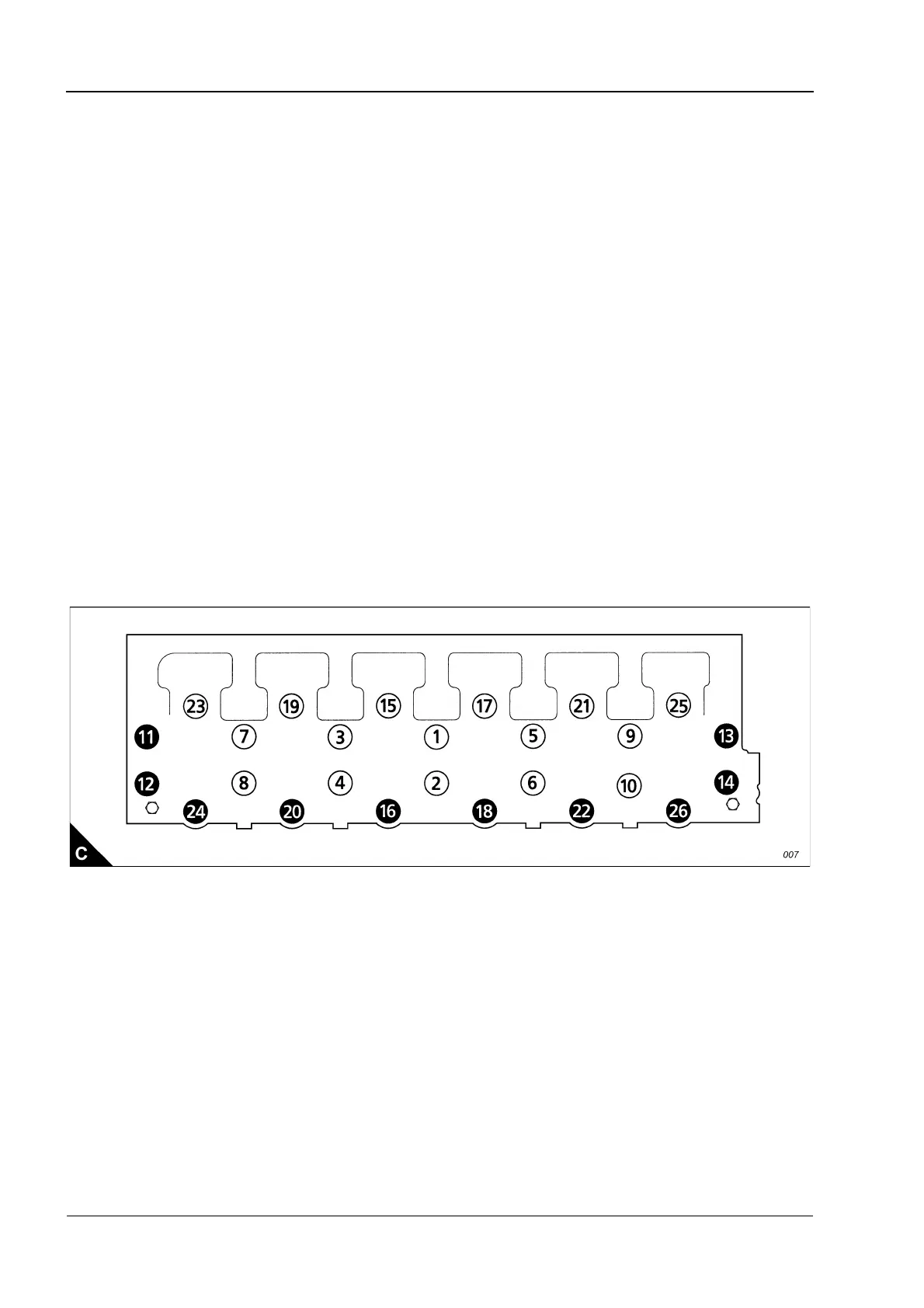
cylinder head bolts and washers. The long bolts must be fitted at the positions shown in the black circles (C).
Use the special socket, GE50020, and the procedure which follows to tighten the bolts correctly:
a. Tighten the cylinder head bolts in the sequence given (C) to a torque of 270 +/- 15 Nm (200 +/- 11 lbf ft).
b. Tighten the cylinder head bolts in the sequence given (C) to a torque of 450 +/- 20 Nm (333 +/- 15 lbf ft).
c. Again, tighten the cylinder head bolts in the sequence given (C) to a torque of 450 +/- 20 Nm (333 +/-
15 lbf ft).
Caution: After the cylinder head assembly has been removed and fitted, it is necessary to check the backlash
between the camshaft and the idler gears. Incorrect adjustment can cause damage to components.
11 Fit the camshaft gear. Check and, if necessary, adjust the backlash between the camshaft gear and the
idler gear, Operation 3-11.
12 Fit the gear case cover, Operation 6-1.
13 Fit the support bracket between the cylinder head and the gear case.
14 Fit the electronic unit injectors, Operation 3-12.
15 Fit the rocker lever and shaft assemblies, Operation 3-2.
16 Fit the exhaust manifold, Operation 9-1.
17 Fit the thermostat housing, Operation 12-10.
18 Remove the covers from the fuel line and the fuel line port on the cylinder head. Connect the fuel line to
the cylinder head and attach the bolt and clamp.
19 Fit the timing sensor and connect the cable.