Operating Manual DTT 6801 Multicontroller (MC) 086100037 © Pfannenberg GmbH Page 20 / 49
3.4.2 DTT cooling unit assembly (installation)
Make cut-outs for the DTT cooling unit
Requirements
- All general requirements are fulfilled, see General assembly requirements
- The cooling unit is de-energized.
Required tools and material
- Saw
- Use a switch cabinet cutter, if applicable
- Protective covers
Procedure
Use a protective cover to protect the switch cabinet from chips.
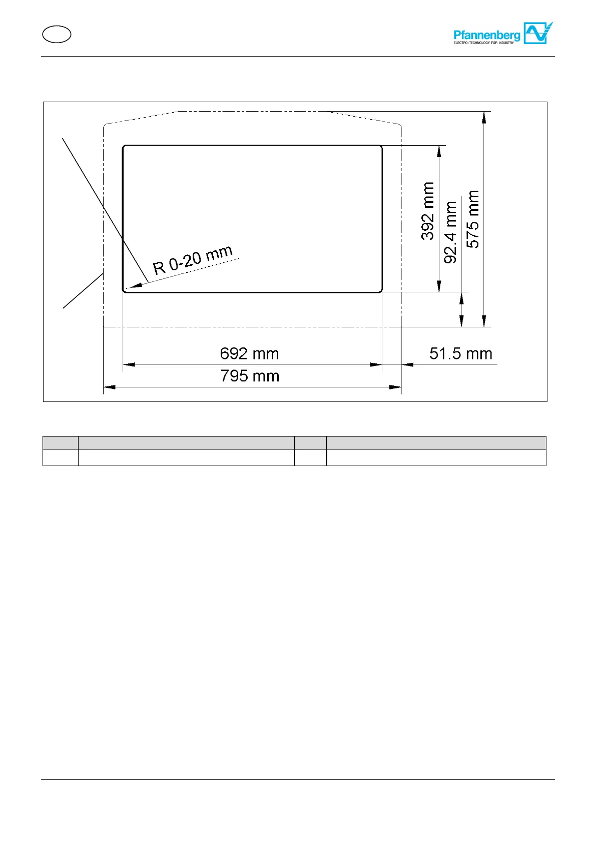
Provide the switch cabinet with cut-outs and holes. For the prescribed dimensions, refer to the figure cut-outs for
the DTT cooling unit.
Deburr the cut edges.
Remove chips and assembly waste from the switch cabinet.
Cut-outs (4) and holes have been made.
Figure17 – DTT switch cabinet cut-out
 Loading...