EasyManuals Logo

Pfannenberg DTT 6801 Series User Manual

Pfannenberg DTT 6801 Series
Go to English
246 pages
To Next Page IconTo Next Page
To Previous Page IconTo Previous Page
Page #76 background imageLoading...
Page #76 background image
Operating Manual DTT 6801 Multicontroller (MC) 086100037 © Pfannenberg GmbH Page 27 / 49
GB
3.5 Electrical connection
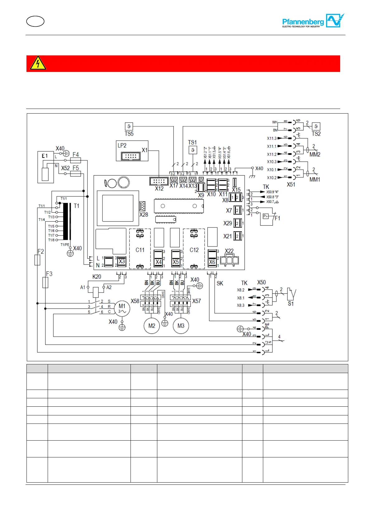
3.5.1 Multicontroller (MC) electrical circuit diagram
DANGER
Life-threatening danger due to electric shock
Live units and exposed connection cables can generate an electric shock and cause severe accidents.
Work on electrical connections must be carried out exclusively by trained, qualified electricians.
Ensure that the unit is voltage-free before routing all electrical connections.
Item
Designation
Item
Designation
Item
Designation
C11
Capacitor condenser fan
(external)
C12
Capacitor evaporator fan
(internal)
E1
Condensate evaporation
F1
High-pressure pressostat
F2-F5
Fuse
LP1
Controller
LP2
Display control unit (MC)
M1
Compressor
M2
Condenser fan (external)
M3
Evaporator fan (internal)
MM1
Multimaster input
MM2
Multimaster output
S1
Door contact
S1.1
Door open
S1.2
Door close
SK
Fault signal contact (1,2)
TK
Door contact / signal (3,4)
TS1
Temperature sensor
(internal)
TS2
Temperature sensor
(external)
TS5
Temperature sensor
(internal)
X40
X42
Ground terminal contact
X50
Mains terminal contact
+ Door contact
+Fault indication
X51
Multimaster terminal contact
+ Temperature sensor
(external)
X52
Heater condensate contact
Max.2,5 mm
2/
AWG 14
Power cable
3x360V 440V 50Hz
3x414V 506V 60 Hz
085 000 45211189-843b
S1.2
S1.1

Table of Contents

Questions and Answers:

Question and Answer IconNeed help?

Do you have a question about the Pfannenberg DTT 6801 Series and is the answer not in the manual?

Pfannenberg DTT 6801 Series Specifications

General IconGeneral
BrandPfannenberg
ModelDTT 6801 Series
CategoryController
LanguageEnglish