Operating Manual DTT 6801 Multicontroller (MC) 086100037 © Pfannenberg GmbH Page 23 / 49
3.4.5 Switch cabinet assembly
Requirements
- The M8 jack rings are screwed into the cooling unit, see Mounting M8 jack rings.
- The cooling unit is secured correctly with lashing straps.
Required tools and material
- Lashing straps, loading crane, if applicable
Procedure
Raise the correctly secured cooling unit slowly and evenly; see figure and DTT cooling unit assembly.
Assembly the cooling in a level position.
Position the cooling unit on the switch cabinet roof and align it with the cut-outs.
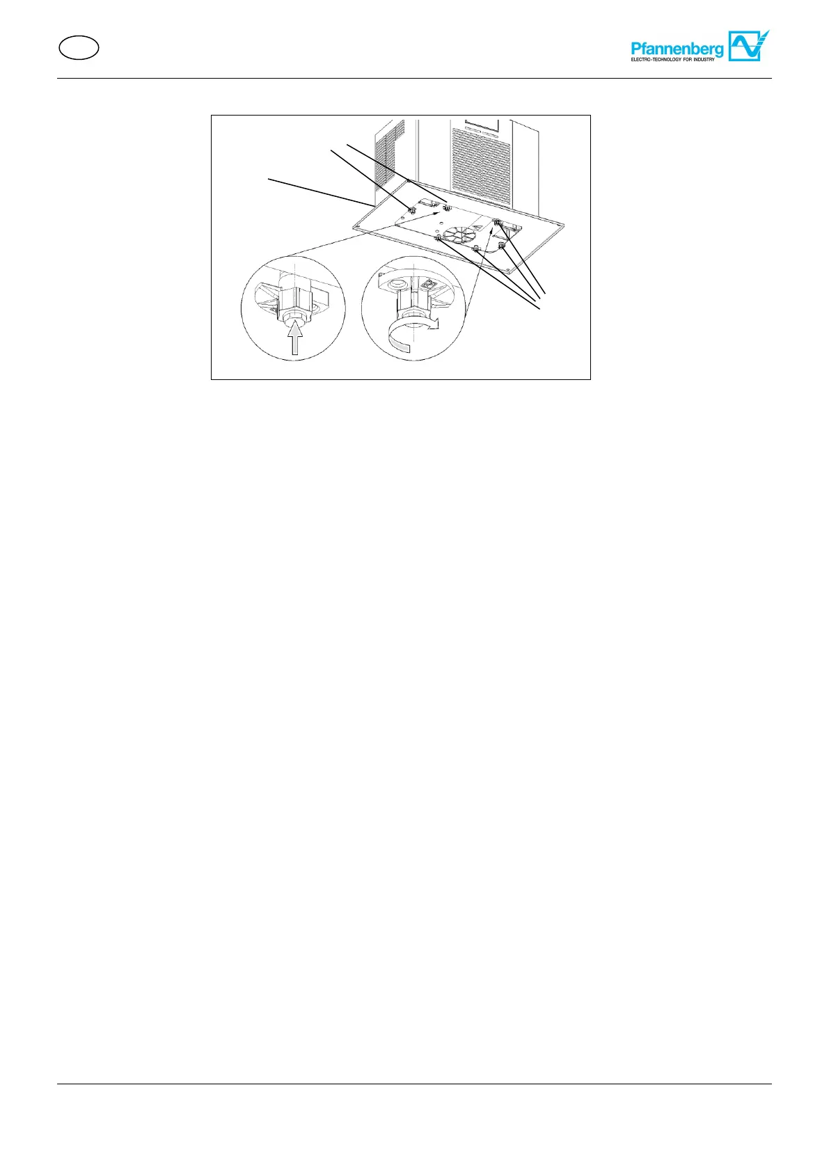
Ensure that the condensate drain (1) is positioned at the lowest point.
Install the condensate drain hose on a consistent decline and without kinks.
The condensate drain hose length must not exceed 3 m.
Check regularly during operation to ensure that the condensate water drains correctly.
Position the cooling unit precisely in the cut-out.
All six casement fasteners (2) on the inside of the switch cabinet; see the figure Cooling unit assembly - detail A.
Screw in all six casement fasteners (2) on the inside of the switch cabinet over the rail to mount the cooling unit;
see the figure Cooling unit assembly - detail B.
The cooling unit is attached to the switch cabinet and ready for electrical connection, see Electrical connection.
Figure 20 – Cooling unit assembly with casement fasteners
 Loading...