Pharma Test Apparatebau AG
Operating Manual
B-24-00100_PT-NODE_v1.0e.docx Page 36 of 64
5.1.1.2 Connecting the Instrument to PT-Node
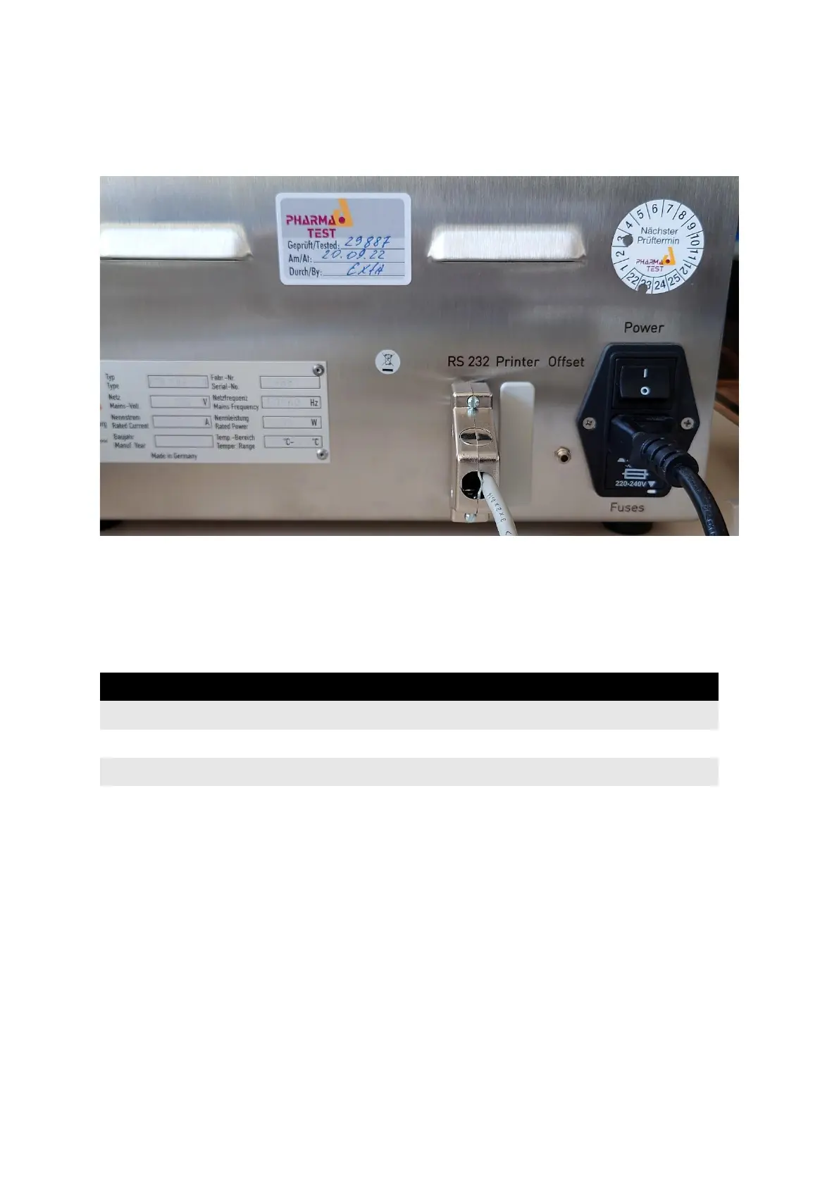
Connect the communication cable (part no. 34-00311) to the port labeled “RS 232” on the
backside of the instrument:
Figure 41: Communication cable connection to PTB 111EP
Connect the other side of the cable to one of the ports of PT-Node. Note the channel number
the port corresponds to.
5.1.1.3 Set the Device Settings on PT-Node
Login to PT-Node as administrator and enter the device menu. Enter the following settings:
Table 6: PT-Node device settings for PTB 111E and PTB 111EP for serial data
Press submit to store the settings.
You can now start measuring with the PTB 111E or PTB 111EP instrument. The serial data
communication is live. This means once the instrument obtains a result it is immediately
sent via the serial interface. Before the first result the instrument sends a start string. From
this line PT-Node recognizes a new measuring run and creates a new file on its internal
storage.