User’s Manual of GS-5220 LCD Series
71
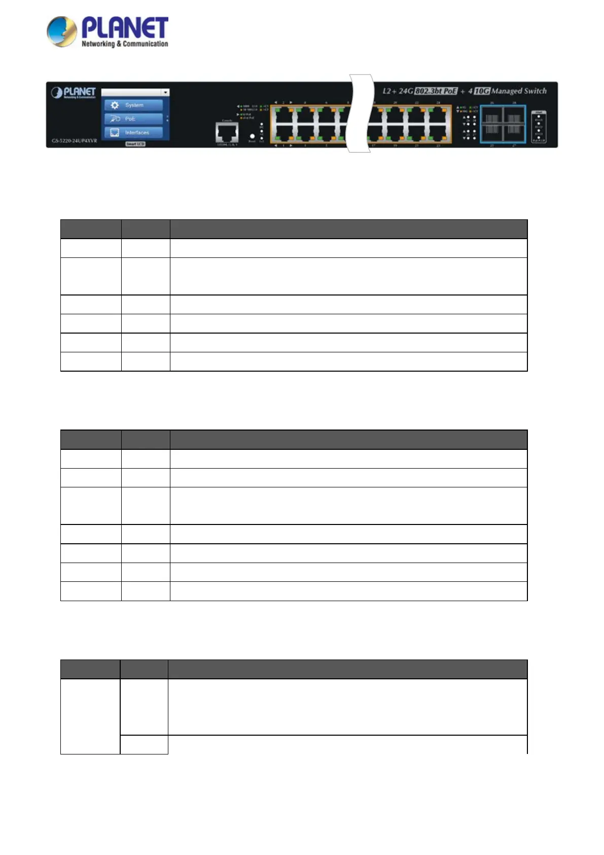
Figure 2-1-30: GS-5220-24UP4XVR LED on Front Panel
System / Alert (GS-5220-24UP4XV)
LED Color Function
PWR Green Lights to indicate that the Switch has power.
SYS Green
Lights to indicate the system is working.
Off to indicate the system is booting.
FAN 1 Red Lights to indicate that FAN1 is down.
FAN 2 Red Lights to indicate that FAN2 is down.
FAN 3 Red Lights to indicate that FAN3 is down.
PoE PWR Red Lights to indicate that the PoE power is down.
System / Alert (GS-5220-24UP4XVR)
LED Color Function
AC Green Lights to indicate that the Switch has power from AC
DC Green Lights to indicate that the Switch has power from DC
SYS Green
Lights to indicate the system is working.
Off to indicate the system is booting.
FAN 1 Red Lights to indicate that FAN1 is down.
FAN 2 Red Lights to indicate that FAN2 is down.
FAN 3 Red Lights to indicate that FAN3 is down.
PoE PWR Red Lights to indicate that the PoE power is down.
10/100/1000BASE-T Interfaces (Port-1 to Port-24)
LED Color Function
Ethernet
Green
Lights: To indicate that the port is operating at 1000Mbps.
Blinks: To indicate that the switch is actively sending or receiving data over
that port.
Orange
Lights: To indicate that the port is operating at 10/100Mbps.
 Loading...