3.4 Fault Management
Fault management is conceptually partitioned into two levels: the system top level, and
interface-specific level. Both levels are alarm-level configurable and can be Major and
Minor. All the alarms are mask-able.
Fault management provides the alarm output through hardware output interface (on the
system front panel) and visible indicator (LED). The alarm/status indications are
automatically generated as a result of certain events/conditions. The IDL-2402 supports
query of all current alarm status. It is also able to keep 256 records of historical alarms
and events respectively.
The IDL-2402 provides the ability to group alarms in a hierarchical alarm presentation
scheme. Alarms of the same rank can exist at the same time. A lower-ranking alarm will
be demoted if a higher-ranking alarm is raised for the same object. For example, if a
far-end LOS is raised on a circuit and then a far-end LPR is raised on the circuit, the LPR
alarm stands and the LOS closes. The alarm hierarchy used in the IDL-2402 system is
shown in the following table:
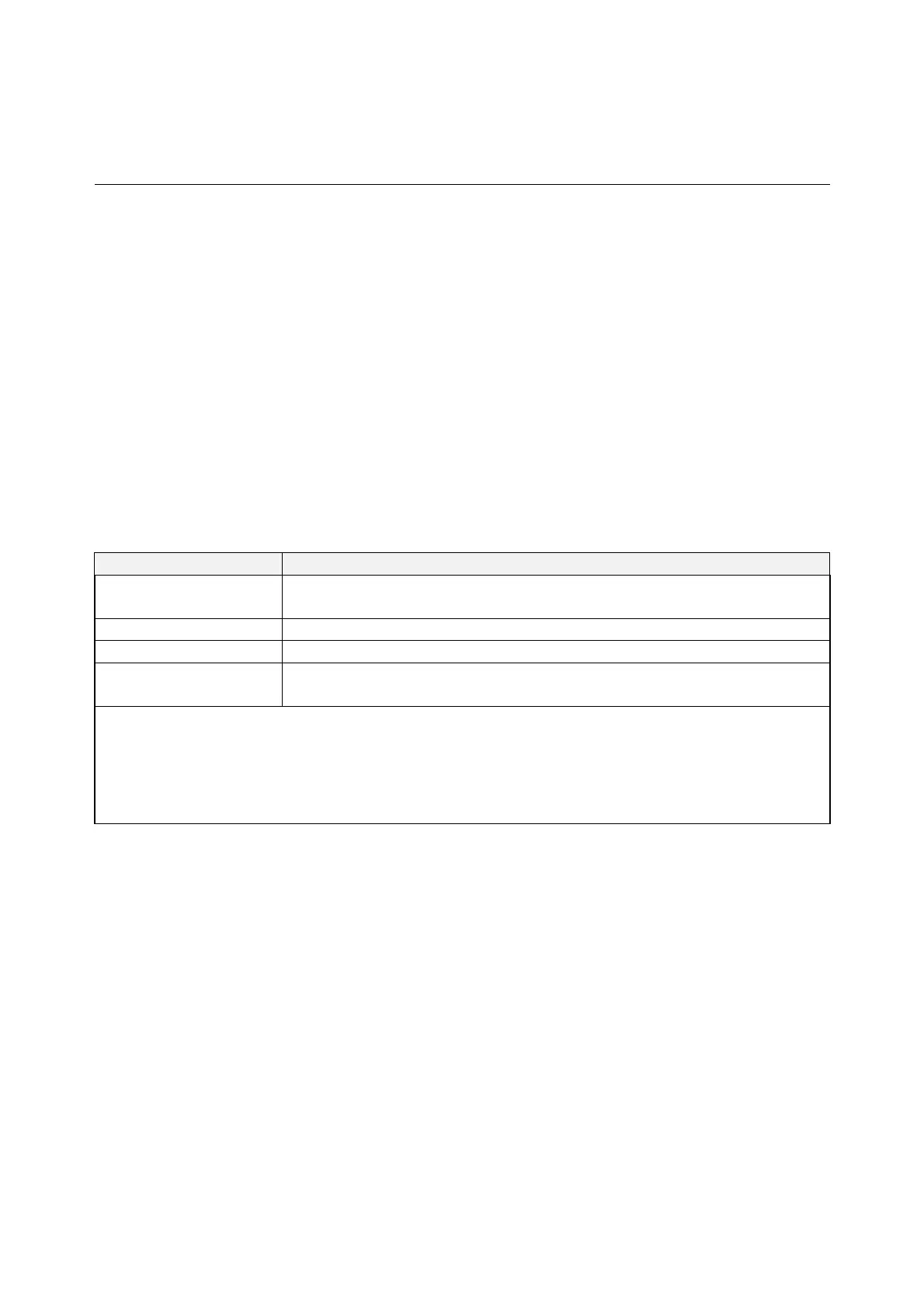
Table 3-3 IDL-2402 Alarm Hierarchy
Priority Alarm Type
Highest all activation failures (ADSL_COMMF_FE or
ADSL_NOPEER_FE)
— far-end LPR
— near-end LOS or far-end LOS
Lowest near-end LOF or far-end LOF (near-end and far-end are
independent; for example, FE-LOS does not restrain NE-LOF)
Note: 1.LOM, LCD, and NCD are not included in the alarm hierarchy; they’re treated
independently.
2.The PM counters LPR, LOS, and LOF follow the alarm hierarchy rule. When
these alarms exist at the same time, only the PM counter of a higher-ranking
alarm will count (the PM counters of other lower-ranking alarms will not).
System Alarms
The IDL-2402 provides the following System alarms:
Fan Failure Alarm
Above Temperature
Below Temperature
Self-test Fail
DSP Fail - you can see which DSP chip is fail from the user interface (Web GUI,
CLI, etc.). There is a number 1 ~ 4 in the alarm message/description
corresponding to the DSP chip 1 ~ chip 4
- 54 -
 Loading...