Planmeca Intra X-ray unit 33
OTHER INSTALLATION ALTERNATIVES
Installation manual
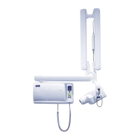
Route the arm and Dixi interconnection cables from the extension arm to the ceiling arm. In case the
Dixi digital intra X-ray system is not installed leave the Dixi interconnection cable into the ceiling arm
as shown on the figure below.
NOTE The Dixi digital intra X-ray system is installed according to the instructions
given in the Dixi digital X-ray systems installation manual.
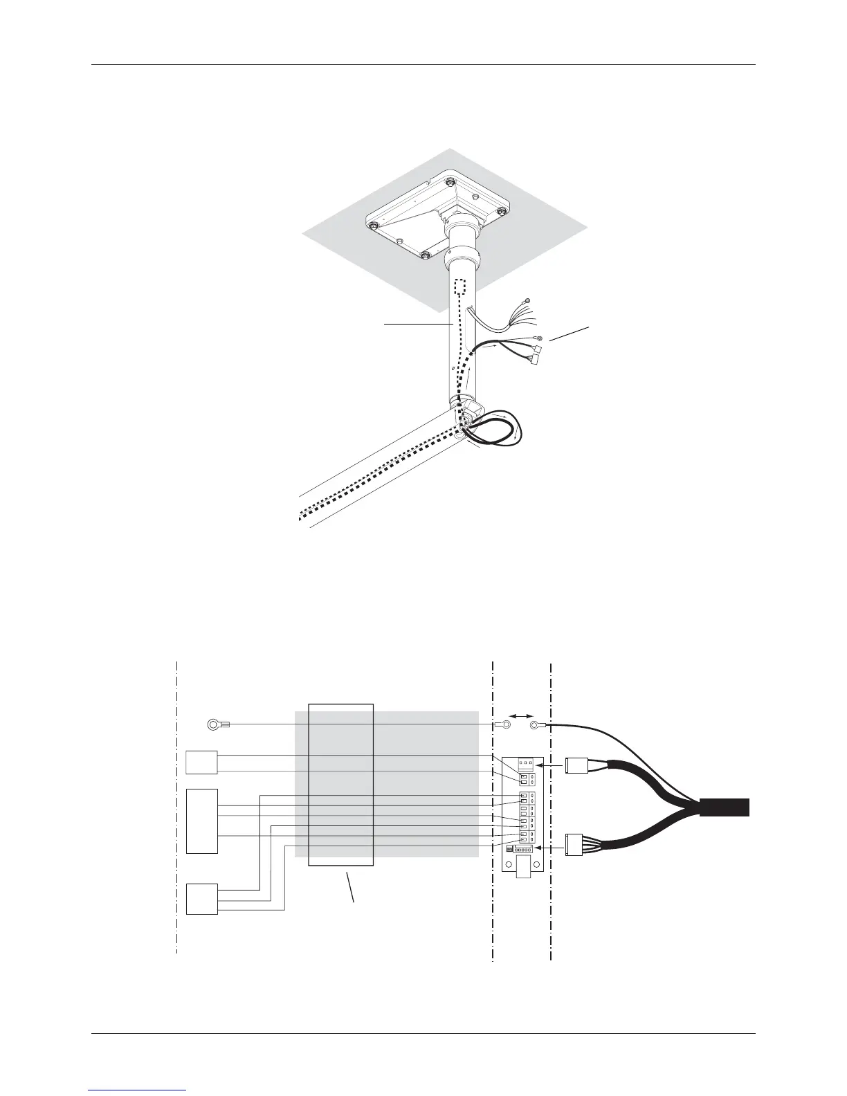
Connect the cables according to the figure below. Note, that it does not matter which way the yellow
leads (HV1 and HV2) are connected to the connectors HV1 and HV2.
Ceiladap8A.eps
Arm cable
Dixi interconnection cable
P6
P7
P9
P8
HV1
HV2
+12V
EXP
KVC
GND
AUX1
AUX2
SCL
ELMP
N.C.
Grn
Extension cable max.12 m
Extension
cable Con-
nectors
Molex-3
Molex-6
Generator PCB
Arm cable (Std.)
HV1
HV2
+12V
EXP
+12V
KVC
GND
SCL
GND
ELMP
ELMP
Gry
Brn
Pink
1
1
2
3
2
3
4
5
6
Molex-3
Molex-6
1
2
3
Screw
terminal
P1
P8
P14
Ye l
Yel / Grn
Wht
Gry
Blk
Red
Brn
Blu
Pink
Ferrite
 Loading...


