Bookletmaker SR 85 February 2001PAGE
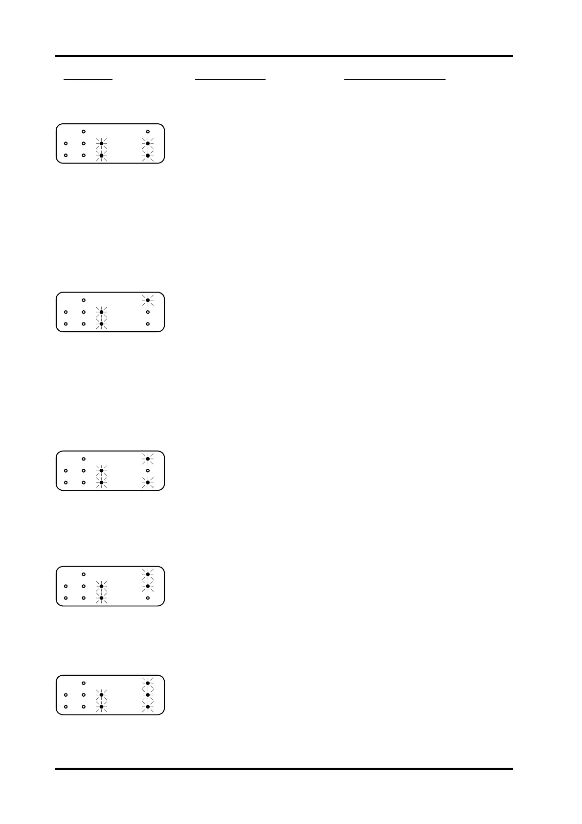
Fault code Possible cause Fault isolating / repair
27
.
Length adjustment
maximum limit switch
SW 3, activated.
Adjusted to maximum paper size.
Adjust to a smaller paper size. It it is
allowed to run the Model 75 adjusted to
the largest paper size
Micro switch defective.
Disconnect the wires from the switch.
Check the function of the switch using a
voltmeter.
Wires defective. Check that the voltage between TP13 on
the controller PCB and common ground is
less than 0.9 VDC when the switch is
activated and greater than 2.2 VDC when
the switch is inactivated.
Controller PCB defective.
If checks above is good, replace the
controller PCB.
28
.
Length adjustment
minimum limit switch
SW 4, activated.
Adjusted to minimum paper size.
Adjust to a larger paper size. It it is
allowed to run the Model 75 adjusted to
the smallest paper size
Micro switch defective.
Disconnect the wires from the switch.
Check the function of the switch using a
voltmeter.
Wires defective.
Check that the voltage between TP11 on
the controller PCB and common ground is
less than 0.9 VDC when the switch is
activated and greater than 2.2 VDC when
the switch is inactivated.
Controller PCB defective.
If checks above is good, replace the
controller PCB.
29
.
Edge staple stop motor
MOT 10, open circuit.
Motor defective. Disconnect the motor connector. Check
the motor for an open circuit using a
voltmeter.
Wires defective. Disconnect the motor connector. Check
the wires for an open circuit using a
voltmeter. Measure from 8 and 9 on
connector J8 to the motor connector.
Controller PCB defective. Replace the controller PCB.
30
.
Edge stapling transport
motor MOT 11,
open circuit
Motor defective. Disconnect the motor connector. Check
the motor for an open circuit using a
voltmeter.
Wires defective. Disconnect the motor connector. Check
the wires for an open circuit using a
voltmeter. Measure from 12 and 13 on
connector J8 to the motor connector.
Controller PCB defective. Replace the controller PCB.
31
.
Length adjustment
motor MOT 6,
open circuit.
Motor defective. Disconnect the motor connector. Check
the motor for an open circuit using a
voltmeter.
Wires defective. Disconnect the motor connector. Check
the wires for an open circuit using a
voltmeter. Measure from 1 and 2 on
connector J8 to the motor connector.
Controller PCB defective. Replace the controller PCB.
Continue FIP 8.1 Self diagnostic system control, Fault code table
8.1.8