TARGAS-1 Operation Manual V. 1.02 101 support@ppsystems.com
2
maximum. This is the same value as the Max CO
2
value for the Graph setting and can be modified under Main > Settings >
Stops the Injection process and returns to Injection – Settings (Step 2).
Process data is not saved to the USB flash drive.
Stops the Injection process and returns to Injection - Settings (Step 2).
Injection Process results are saved to the USB flash drive.
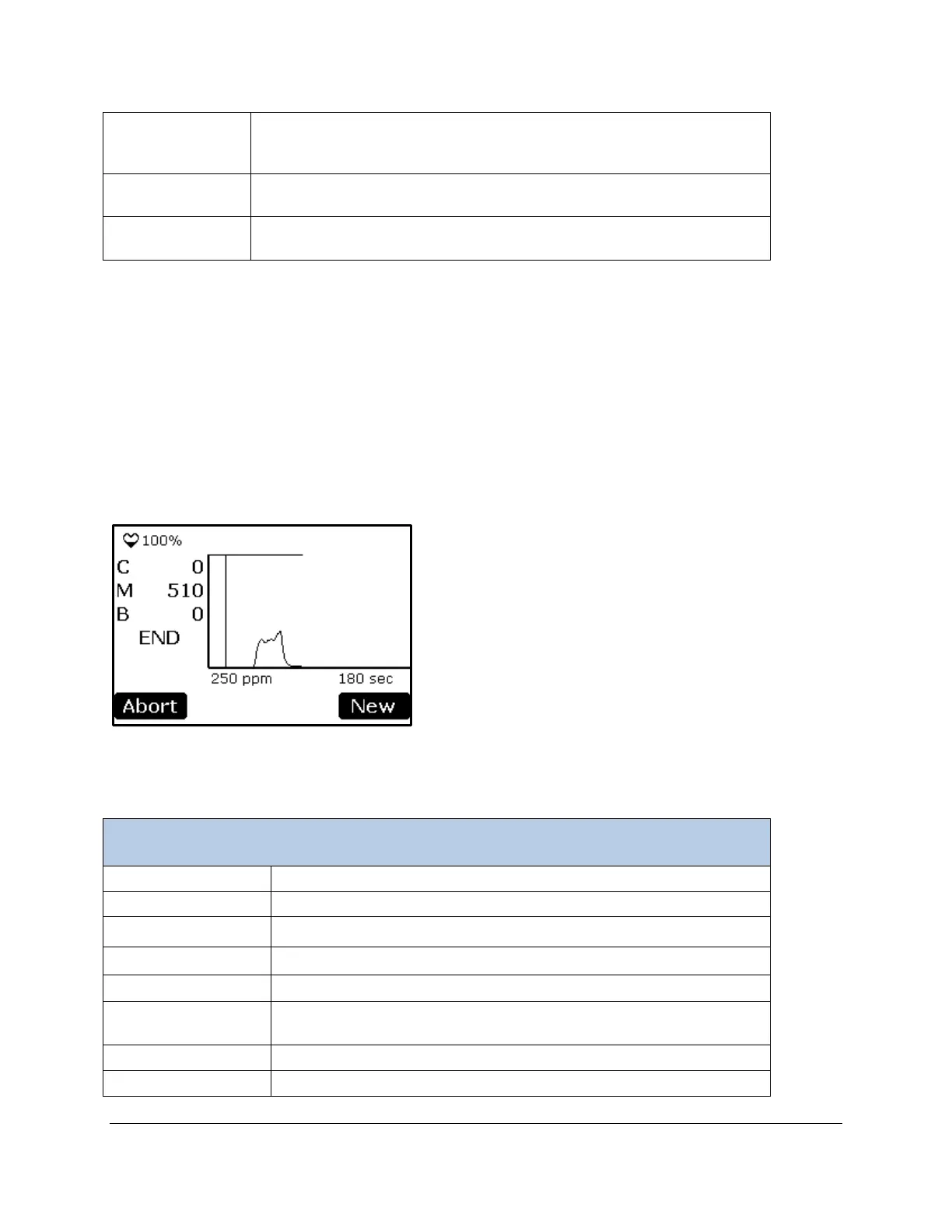
If the baseline (B) does not drop to either 0 or a very small number (typically 1-3 ppm), then there is either
a leak in the system, or the system has not adequately “zeroed”. Try aborting the process, wait 2-3
minutes, and try again. If the problem persists, check the injection setup for leaks and ensure that the
absorber column is properly seated and contains fresh soda lime.
Injection – Injection Phase (Step 6)
During the Injection Phase, the syringe should be slowly and steadily injected into the airstream through
the septum. The injection rate should not exceed 3 ml/second to avoid over-pressurization of the system
(in other words, it should take the user at least 3 seconds to inject a 10 ml syringe).
Pulses to indicate that the system is powered on (power status).
Percentage of battery life remaining (%).
2
concentration in tubing (ppm).
2
concentration inside syringe (ppm).
INJT Indicates that the process is in the injection phase. END
indicates CO
2
concentration calculations have been terminated.
Time (seconds). It is fixed at 180 seconds.
CO
2
concentration in tubing (ppm).