Do you have a question about the PP Systems EGM-5 and is the answer not in the manual?
Registering new customers for updates and access to protected web content.
Details for contacting PP Systems for support and service.
Instructions for checking and storing the equipment upon receipt.
Information on how EGM-5 data is saved to a USB flash drive.
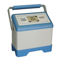
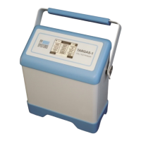
Explanation of the EGM-5's design and operational principles.
Details on the EGM-5's built-in O2, H2O sensors and WiFi capability.
Information on the Apogee Quantum sensor for PAR measurement.
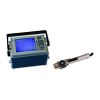
Details on the TRP-3 probe for temperature and PAR measurements.
Description of the chamber for soil CO2 efflux measurements.
Description of the chamber for canopy CO2 flux measurements.
Details on the probe for measuring soil temperature.
Information on the combined sensor for soil moisture and temperature.
Technical details of the internal rechargeable battery pack.
Specifications for the external power adapter.
Overview of the EGM-5's 2.7" EPD touch panel features.
How to navigate the EGM-5 interface using the touch display.
Identification of ports and controls on the rear panel of the EGM-5.
Connection point for external power supply.
Indicator for external power connection status.
Ports for gas inlet and outlet connections.
Settings and control for the internal air sampling pump flow rate.
Port for connecting USB flash drives for data storage.
Port for connecting the EGM-5 to a PC for data transfer.
Ports for connecting external sensors and accessories.
Terminal for analog CO2 output signal.
Terminal for external analog sensor input.
5V power output for external sensors.
Terminal connections for alarm relay outputs.
Terminal for analog voltage output of CO2 reading.
Terminal for general-purpose analog voltage input.
Relays activated by CO2 alarm conditions.
Information on the CO2 scrubbing desiccant and its maintenance.
Description of the EGM-5 touch display interface.
Explanation of the heartbeat icon and display update speed.
Displays the current CO2 concentration reading.
Shows real-time values for CO2, H2O, O2, Temp, Flow, Pressure.
Displays parameters from connected external probes.
Graphical representation of CO2, H2O, or O2 concentration over time.
Access to four submenus for configuring EGM-5 settings.
System diagnostics for troubleshooting hardware issues.
Options for running specific measurement processes (SRC, CPY, etc.).
Procedures for calibrating the CO2, O2 sensors, and touch screen.
Access to version information and contact details.
Configuration for automatic or manual zeroing of the instrument.
Setting low and high CO2 alarm points.
Indicates replacement of the absorber material.
Adjusting pump power and viewing flow rate.
Enabling or disabling audible alarms.
Configuring external probe connections.
Options for setting zero type and time interval for zeroing.
Selection of Automatic, Manual, or User Set zero types.
Setting the interval for user-defined automatic zeros.
Configuring low and high CO2 alarm thresholds and relay behavior.
Setting the threshold for the low CO2 alarm.
Setting the threshold for the high CO2 alarm.
Resetting the absorber column usage percentage.
Adjusting the pump power to control flow rate.
Setting the power level for the air sampling pump.
Enabling or disabling the audible alarm beep.
Toggling audible alarms on or off.
Viewing and changing probe types connected to ports.
Configuring the type of probe connected to Port 1.
Information on probe compatibility for Port 2.
Configuring analog output voltage settings.
Setting the CO2 averaging method and limit.
Adjusting the maximum CO2 value for the graphic display.
Assigning a unique identifier to the EGM-5.
Configuring the CO2 concentration mapped to the analog output voltage.
Adjusting the CO2 averaging window and limits.
Setting a unique identifier for the EGM-5 for multi-unit use.
Setting the maximum CO2 value displayed on the graph.
Configuring data format and interval for host communication.
Configuring data format and interval for WiFi transmission.
Configuring data format and interval for USB memory stick.
Setting the port connection (USB or WiFi).
Restoring WiFi settings to factory defaults.
Turning the WiFi power on or off.
Controlling measurement data format and transmission interval to a host.
Controlling data transmission interval via WiFi.
Controlling data format and interval for saving to flash drive.
Setting the port connection type for the EGM-5.
Initializing the WiFi system to original factory defaults.
Enabling or disabling the WiFi device power.
Setting the system clock (date and time).
Initializing the EGM-5 to its factory default settings.
Placing the EGM-5 into a low-power mode for transport.
Initiating a measurement using the SRC chamber.
Confirming the initiation of the SRC measurement process.
Defining volume and area parameters for the SRC process.
Setting end conditions (time, CO2 change) for the SRC process.
Defining plot number for SRC measurements.
Instructions for preparing the SRC chamber.
Placing the SRC chamber on the soil to begin measurement.
Displaying real-time values and graphical data from the SRC session.
Initiating a measurement using the CPY chamber for canopy CO2 flux.
Confirming the initiation of the CPY measurement process.
Defining volume and area parameters for the CPY process.
Setting end conditions for the CPY process.
Defining plot number for CPY measurements.
Instructions for preparing the CPY chamber.
Placing the CPY chamber on the soil to begin measurement.
Displaying real-time values and graphical data from the CPY session.
Using custom chambers for measurements with user-defined parameters.
Confirming the initiation of a custom measurement process.
Defining volume and area parameters for custom chambers.
Setting end conditions for custom measurement processes.
Defining plot number and air temperature for custom measurements.
Instructions for preparing the custom chamber.
Placing the custom chamber on the soil to begin measurement.
Displaying real-time values and graphical data from the custom session.
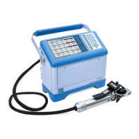
Explanation of how gas samples are measured using injection.
Confirming the initiation of the gas injection measurement process.
Setting syringe volume and correction factor for injection.
Defining sample number and preparing the syringe for injection.
Option to perform a zero before injection measurements.
Recording baseline CO2 concentration before sample injection.
Injecting the gas sample into the EGM-5 airstream.
Performing static gas sampling measurements.
Confirming the initiation of a static measurement process.
Displaying real-time values and graphical data from a static session.
Initiating the CO2 sensor recalibration procedure.
Initiating the O2 sensor recalibration procedure.
Calibrating the EGM-5 touch screen display for accurate input.
Instructions for connecting calibration gas to the EGM-5.
Recalibrating the internal O2 sensor of the EGM-5.
Calibrating the touch screen display for accurate input.
Viewing A/D counts and initiating zeros for the CO2 detector.
Switching between Measure and Zero modes for diagnostics.
Displaying the last seven zero values for analysis.
Displaying the total operating hours of the controller and IRGA.
Monitoring battery charge, voltage, current, and estimated time remaining.
Displaying various voltage readings from the instrument.
Accessing advanced diagnostic features via password.
Viewing hardware and software serial and version numbers.
Displaying contact information for PP Systems.
Details on using USB flash drives for data storage and file naming.
Overview of data fields available for different measurement modes.
Connecting the EGM-5 to a host via USB cable.
Connecting the EGM-5 wirelessly via WiFi.
Methods for reading data and changing settings (Command Set, GAS, Web Pages).
Using ASCII commands for direct communication with the EGM-5.
Automatic text strings sent by EGM-5 under specific conditions.
Reference table for standard EGM-5 commands and their functions.
The initial screen displayed when accessing EGM-5 via web pages.
Overview of informational screens for monitoring data.
Interactive screens for changing EGM-5 settings.
Establishing a wireless connection using the EGM-5's SoftAP mode.
Connecting the EGM-5 to a LAN for network access.
Instructions for maintaining the external air filter.
Maintenance of the absorber column, foam filters, and soda lime.
Procedures for accessing internal components for troubleshooting.
Details on the rotary vane sampling pump used in the EGM-5.
Information about the infrared source lamp and potential issues.
Instructions for replacing the internal hydrophobic filter.
Information regarding the rechargeable Li-Ion battery pack.
Explanation of principles for measuring soil CO2 efflux and canopy flux.
How the EGM-5 software calculates respiration rates.
Method for compensating CO2 measurements for water vapor effects.
Conversion of CO2 flux units for soil measurements.
List of cited literature relevant to soil respiration.
Identification codes for country-specific transmitter compliance.
Safety certifications and compliance information.
FCC compliance statement regarding radio frequency interference.
Warning regarding modifications to the equipment.
Statement on FCC compliance with radiation exposure limits.
| Brand | PP Systems |
|---|---|
| Model | EGM-5 |
| Category | Measuring Instruments |
| Language | English |