EGM-5 Operation Manual V. 1.04 58 support@ppsystems.com
At this stage, the SRC chamber should be held in the air to allow it to flush out prior to placing it on the
soil. During the flushing the internal fan of the SRC is sped up to help flush. The number at the top right of
the screen (24 in this case) is the countdown. CO
2
concentration is displayed during this step. When
completed, SRC Step 6 will be displayed.
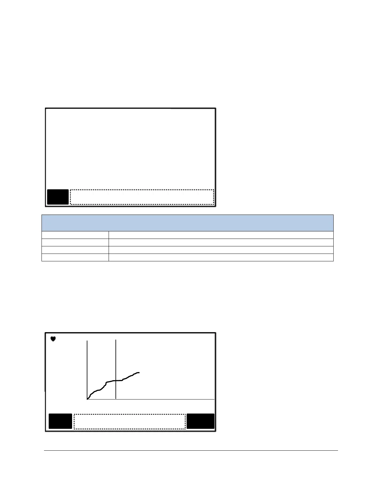
SRC – Start Measuring (Step 6)
This screen informs the user to place the chamber on the soil to commence measurement.
SRC – Start Measuring Menu
Current measurement of CO
2
concentration (ppm).
Countdown in seconds, from 10 to 0.
Stops the SRC process and returns to SRC – Other Settings menu (Step 4).
Any information or error messages are displayed here.
At this stage, the SRC chamber should be placed on the soil. The internal fan is set to a low speed to
provide an even concentration of CO
2
. The number at the top right of the screen (5 in this case) is the
countdown. CO
2
concentration is displayed during this step. When completed, the Data Plot Screen will
be displayed.
Data Plot Screen (Step 7)
This screen displays present values and a graphical representation of the data gathered during the
current session.