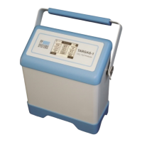
TARGAS-1 Operation Manual V. 1.02 32 support@ppsystems.com
Gas Ports
There are 4 gas ports on the TARGAS-1. Each port is designed for use with 1/8” (.125”) ID tubing or a
mating quick disconnect.
• GAS OUT: Exhaust air from the IRGAs
• GAS IN: Reference air entering the IRGAs (when PLC5 is used) or sample air when in absolute
or closed modes
• REF OUT: The (conditioned) air from the TARGAS-1 (when PLC5 is used) or exhaust air when in
absolute or closed modes
• AIR IN: The air that is drawn in from the ambient and used by the TARGAS-1 for the PLC sample
air (Reference)
NOTE: the REF OUT must be linked to the GAS IN when using a PLC5 or PLC3 leaf cuvettes for
measurement of leaf gas exchange. See Back of TARGAS-1 on page 22. The link pipe must be
removed when using the SRC-2 Soil Respiration Chamber or the CPY-5 Canopy Assimilation Chamber.
When using these accessories both the GAS IN and GAS OUT ports are used and the link pipe is not
required.
When using the TARGAS-1 as a stand-alone CO
2
/H
2
O analyzer, the sampling line should be fitted to the
GAS IN port and the GAS OUT port should be left open to atmosphere to allow the sample air to exhaust
without restriction. This does not apply when using some optional accessories (e.g., the SRC-2 Soil
Respiration Chamber or the CPY-5 Canopy Assimilation Chamber).
Flow Rate
The TARGAS-1 features an internal electronic flow sensor for controlling flow rates.
Important Note
If the flow rate cannot be maintained, a “low flow" error message will be displayed in the status box.
Typically this is the result of flow restriction caused by either the external air filter (if applicable) or a
blocked internal hydrophobic filter located inside the TARGAS-1 enclosure. First, replace the external air
filter (if applicable) connected to the GAS IN port to see if this corrects the problem. If it doesn’t then the
likely problem is a blocked internal hydrophobic filter See Hydrophobic Filter on page 145 for information
related to changing this filter.
USB Flash Drive Port
A USB Flash Drive Port is available on the back panel to allow users to save data directly to a USB flash
drive (also commonly referred to as a “thumb drive” or “memory stick”). When a USB flash drive is
inserted into the USB port, the LED indicator will first turn red in recognition of the USB flash drive and
then it will flash green indicating that data is being saved to it automatically. If the indicating LED is a
steady green then data is not being saved because the “Interval (sec)” is likely set to 0 under Interval
Settings.
USB PC Port
The USB PC Port (USB Mini-B) can be used to connect the TARGAS-1 to a PC. Measured data is
continuously sent through this port. The PP Systems’ GAS software or a terminal emulation program (i.e.
HyperTerminal) can then monitor the measured data. GAS software is supplied on the USB flash drive
supplied with the TARGAS-1 and it is also available for free download from our website. See GAS (Gas