TARGAS-1 Operation Manual V. 1.02 15 support@ppsystems.com
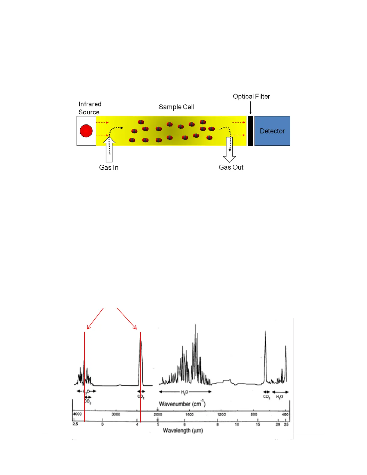
• Infra-red source
• Sample cell of known path length and volume
• Optical interference filter
• Infra-red detector
The theory itself is quite simple – light from mid-infra-red wavelengths is produced by the source and
pulsed through a gold plated cell. The interference filter narrows the bandwidth of the IR source received
by the detector to the signature wavelength absorbed by the target gas molecule, e.g. CO
2
. The CO
2
and
H
2
O cells each employ a unique optical filter. As the sample gas fills the cell, it absorbs IR, and the
reduction in IR source strength is measured instantaneously by the detector. The higher the target gas
concentration, the lower the infra-red signal received at the detector, as defined by the Lambert-Beer Law
of Attenuation.
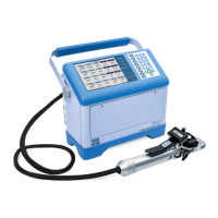
Both H
2
O and CO
2
molecules have diverse absorption spectra, so we use two prominent absorption
peaks, seen below at 2.60 and 4.26 µm, respectively. The TARGAS-1 electronics could be considered
the fifth component, which processes raw analog-to-digital (A/D) information from the IRGAs detectors,
accurately translating this information into gas concentrations.
The TARGAS-1 detectors are optimized for these
wavebands for H
2
O (2.60 µm) and CO
2
(4.26 µm)