SECTION 06A: H3 SERIES ELECTRICAL
PA1621 Maintenance Manual All Series | January 2017
13
3. ELECTRICAL COMPARTMENTS
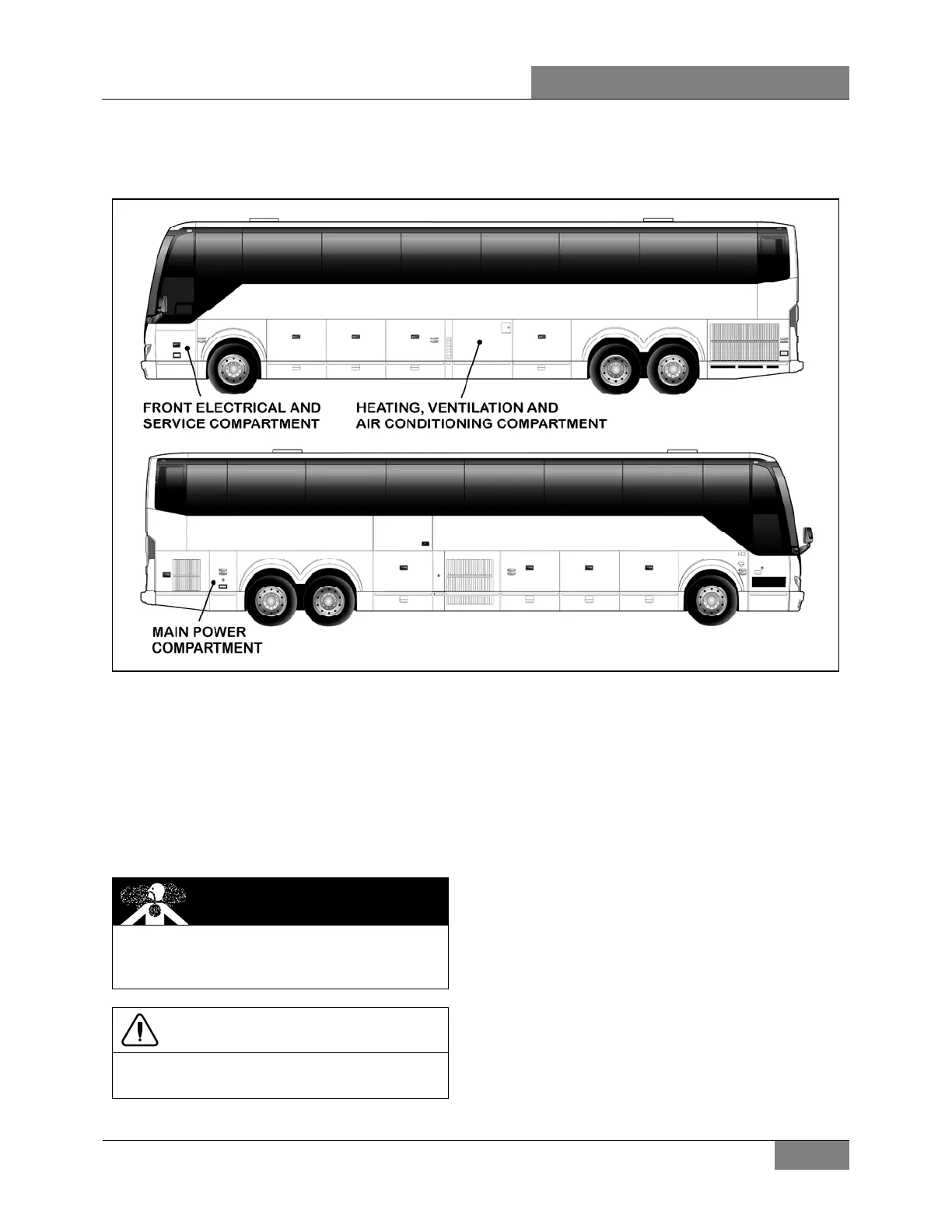
FIGURE 4: ELECTRICAL COMPARTMENTS
3.1 MAINTENANCE
A corrosion inhibitor has been sprayed on
certain electrical components in order to protect
them from corrosion. Refer to procedure
SAV00002E at the end of this section for
recommended products and where they are
used.
DANGER
Use sprayed sealer in a well ventilated area.
Do not smoke. Avoid prolonged contact with
skin and breathing of spray mist.
CAUTION
Never put grease or other product on the
multiplex modules connector terminals.
3.2 MAIN POWER COMPARTMENT
The main power compartment is located on rear
R.H. side of vehicle behind the rear
wheelhousing. This compartment contains the
following components (Figure 5 & Figure 6):
Four 12-volt batteries;
Main circuit breakers for 12-volt and 24-volt
electrical system;
Voltage regulator (if applicable);Battery
equalizer;
Battery Charger (optional);
Battery master relay (R1) & battery master
switch;
TCM (Transmission Control Module);
Secondary circuit breakers;
Relays;
Rear fuse box known as VECR (Vehicle
Electrical Center Rear);
Multiplex modules: I/O-A, I/O-B;
 Loading...