SECTION 12: BRAKE AND AIR SYSTEM
PA1621 Maintenance Manual All Series | January 2017
31
limit the excessive brake pressure produced by
the driver in the appropriate brake chamber.
Maintenance
No specific maintenance is required. The ECU
is not serviceable. When found to be defective,
replace.
FIGURE 32: ABS ECU LOCATION
CAUTION
In order to protect the ABS electronic control
unit from voltage surges, always disconnect
before performing any welding procedure on
vehicle.
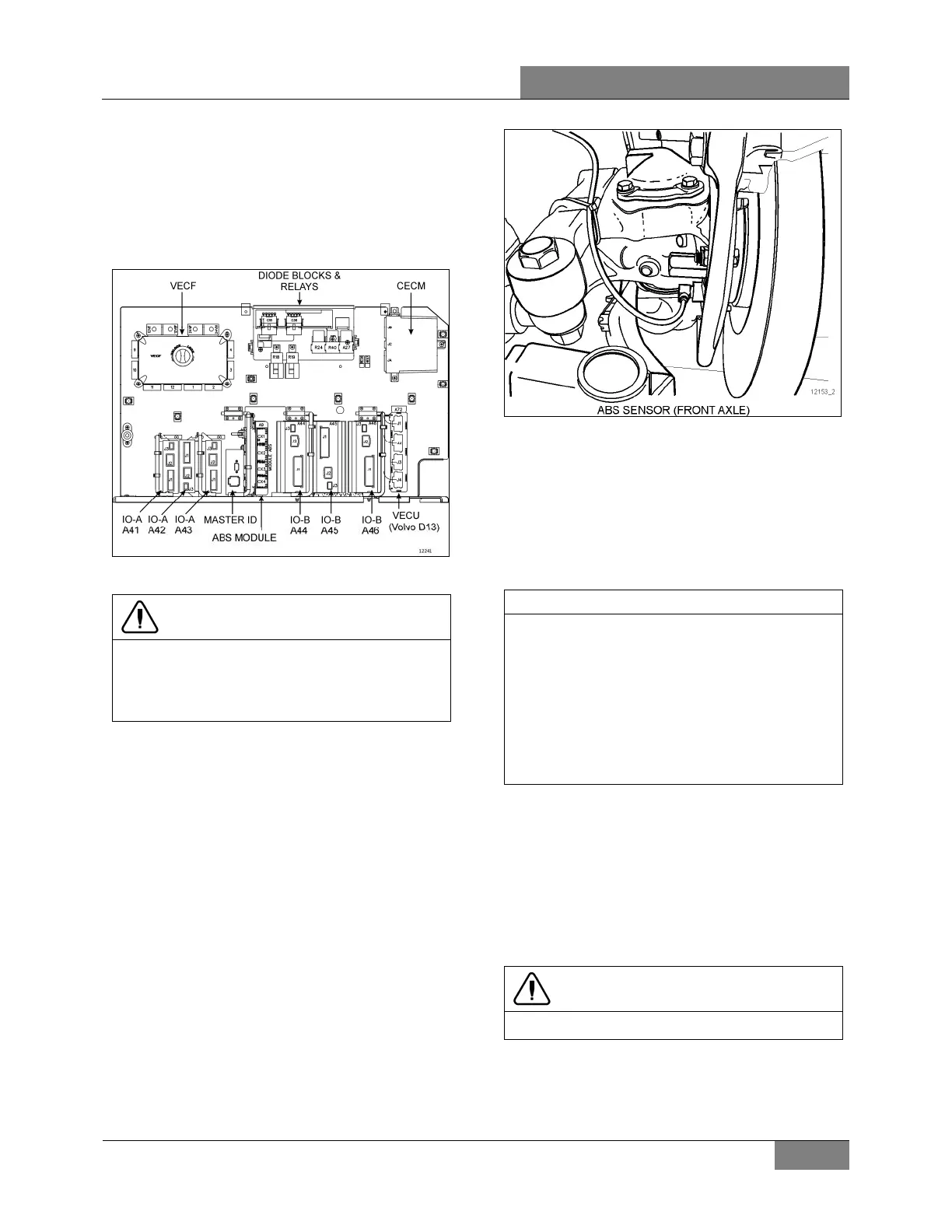
31.4 SENSORS
The sensors are mounted on the front and drive
axle wheel hubs (Figure 33). The inductive
sensors consist essentially of a permanent
magnet with a round pole pin and a coil. The
rotation of the toothed wheel alters the magnetic
flux picked up by the coil, producing an
alternating voltage, the frequency of which is
proportional to wheel speed. When wheel
speed decreases, magnetic flux decreases
proportionately. Consequently, the electronic
control unit will command the solenoid control
valve to decrease the pressure at the corre-
sponding brake chamber.
FIGURE 33: ABS SENSOR LOCATION
Maintenance
No specific maintenance is required for sensors,
except if the sensors have to be removed for
axle servicing. In such a case, sensors should
be lubricated with special grease (Prevost
#680460) before reinstallation. Refer to
paragraph “Sensor Installation” for details.
NOTE
The resistance value, when sensors are
checked as a unit, must be equal to 1,75
kohms. To check the sensors for proper
output voltage after the sensors and toothed
wheels have been assembled to the axle,
connect a suitable AC voltmeter across the
output terminals. With the hubs rotating at 30
rpm, the output voltages should read from 50
to 1999 mV to be acceptable.
Sensor Installation
The following procedure deals with sensor
installation on the axle wheel hubs. Read
procedure carefully before reinstalling a sensor,
as its installation must comply with operational
tolerances and specifications.
1. Apply recommended lubricant (Prevost
#680460) to spring clip and sensor.
CAUTION
Use only this type of grease on the sensors.
2. Insert spring clip in the holder on hub. Make
sure the spring clip tabs are on the inboard
side of the vehicle. Push in until the clip
stops.
 Loading...