SECTION 22: HEATING AND AIR CONDITIONING
PA1621 Maintenance Manual All Series | Section Revised November 2017
65
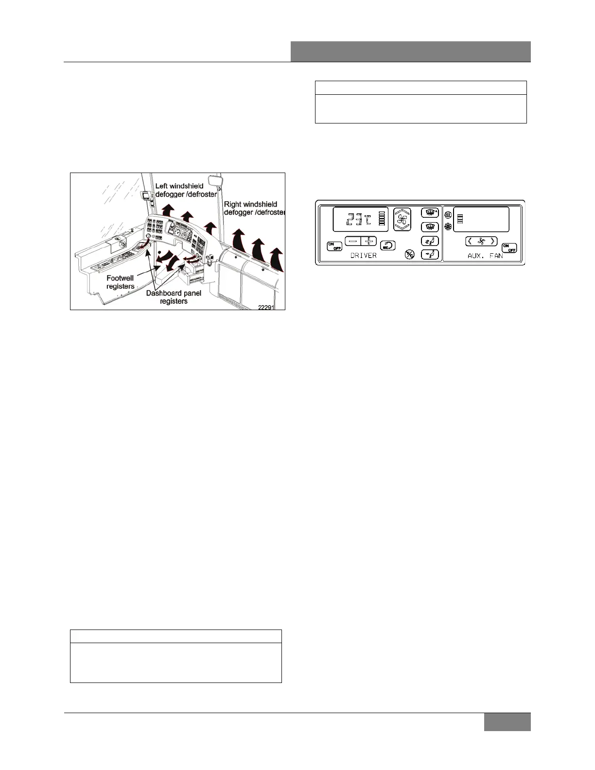
Both right and left discharge ducts defrost one
half of the windshield. The driver can also divert
his air flow to the dashboard, from which he can
direct vent to his upper body with adjustable
HVAC register and to his feet with the
appropriate button (see FIGURE 82 and
Owner’s manual).
FIGURE 82: DRIVER’S UNIT AIR CIRCULATION
7.3.1 Auxiliary Unit
H3 VIP vehicles equipped with the small HVAC
system are equipped with an auxiliary system
that provides five additional registers. Three are
located behind the driver’s seat and the other
two are located near the entrance door, at
bottom of first lateral window. The auxiliary unit
comes with cooling and heating coils, fan and
discharge ducts.
7.4 SYSTEM OPERATION
7.4.1 Driver’s Unit
The small HVAC system driver’s unit is similar to
the central HVAC system driver’s unit, except
that the circulating pump is located on the ceiling
of the spare wheel compartment (Figure 9).
On H3 VIP series vehicles, an auxiliary unit is
added in series on the return line of the small
system, it increases the whole system heating
capacity and gives the driver more options.
The temperature control in the driver’s area is
provided directly by the HVAC control unit
mounted on the dashboard R.H. side.
NOTE
X3 Series - The driver’s area air temperature
sensor is located behind the grill of the R.H.
side console.
NOTE
X3 Series - The outside air temperature sensor
is located near the RH headlight.
7.4.2 Auxiliary Unit - H3 VIP Vehicles Only
The temperature control is provided by the small
system HVAC control unit. The R.H. portion of
the HVAC control unit enables to actuate the
auxiliary unit and to regulate the fan speed.
FIGURE 83: CONTROL UNIT - SMALL HVAC SYST. 22286
7.5 REFRIGERANT RECOVERY
The release of refrigerant into the atmosphere
must be avoided. Whenever refrigerant is to be
released from the air conditioning system, a
refrigerant recovery unit must be used to recover
the refrigerant. This refrigerant can then be
recycled and reused, which is both
environmentally safe and economical.
For complete system recovery, any of the High
and Low service ports can be used. Energize
liquid solenoid valve and measure the quantity
of oil recovered. For the compressor only, use
the service valve port and close the valves. The
service valves open permits full flow of
refrigerant to service port. Service valve closed
permits flow of refrigerant from compressor to
service port.
7.6 EVACUATING SYSTEM PRIOR
ADDITION OF REFRIGERANT (DRIVER’S OR
AUXILIARY SYSTEM)
When a system has been opened for repairs,
change the filter-dryer and evacuate the system.
Use the high-pressure service port and low-
pressure port. It would be good practice to open
the solenoid valve.
1. Connect two hoses equipped with a micron
gauge between the high-pressure service
port, the low-pressure service port and the
vacuum pump.
2. With the unit service valves open and the
vacuum pump valves open, start the pump
and draw the manifold and hoses into a
very deep vacuum (700 microns).
3. Close manifold valve
 Loading...