SECTION 06B: X3 SERIES ELECTRICAL
PA1621 Maintenance Manual All Series | Jul 2017
65
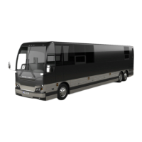
7.2 DID DISPLAY
In the DID you will find the percentage of trip
made with regenerated electricity displayed
along with the instantaneous fuel consumption.
This value is reset each time the engine is
restarted.
FIGURE 47: PRIME DID DISPLAY
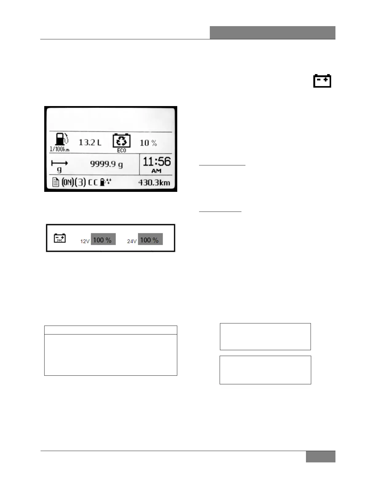
In addition to the standard voltage gage, the DID
also includes a state of charge gage for the
batteries:
FIGURE 48: BATTERY STATE OF CHARGE
This gage displays the level of charge for the
12V and 24V battery banks in percentage.
8. BOSCH ALTERNATORS
Three 24-volt 150A, self-regulated, belt driven,
air-cooled HD 10 BOSCH alternators are used in
the 24 volt electrical system.
NOTE
For the complete removal/installation
instructions, refer to Maintenance Information
MI16-17 Bosch HD10 alternator removal
and installation included at the end of this
section.
8.1 IDENTIFYING A DEFECTIVE
ALTERNATOR
When an alternator is not charging,
the charging system warning light will
illuminate.
charging
system
warning
light
8.1.1 Alternator identification
Cold side alternators are the one found on the
A/C compressor side. The hot side alternators
are the one located on the engine turbo side.
Cold Side (R.H.):
ALTERNATOR Up RH= upper right
ALTERNATOR Low RH=lower right
ALTERNATOR Ext RH= above small A/C comp.
(MTH only)
Hot Side (L.H.):
ALTERNATOR Up LH= upper left (MTH only)
ALTERNATOR Low LH=lower left
8.1.2 Identifying a defective alternator using
the instrument cluster DID
1. On the DID (Driver Information Display),
select DIAGNOSTICS menu.
2. Select VIEW ACTIVE FAULTS and then
ELECTRICAL SYSTEM.
3. The active electrical system faults will
appear. Scroll through the active faults. You
will find one of the following messages:
MID (188) ELECTRICAL SYSTEM
PSID 34 ALTERNATOR Low RH
FMI (5) OPEN CIRCUIT
MID (188) ELECTRICAL SYSTEM
PSID 35 ALTERNATOR Up RH
FMI (5) OPEN CIRCUIT
8.1.3 Identifying a Defective Alternator –
Back-probing AE49 & AE52 Multiplex
Modules Method
Prerequisite conditions:
a) Engine running;
 Loading...