PA1621 Maintenance Manual All Series | January 2017
2. Remove tie rod ball stud by tapping on
steering arm and bell crank or idler arm with
brass hammer, while using a sledge
hammer to absorb shocks.
If tie rod end assemblies are damaged in any
way, they must be replaced
4.7.2 Installation
1. Install socket end assemblies on tie rod. Be
sure both ends are threaded an equal
distance into the tube.
2. Make sure threads on stud and in stud nut
are clean and not damaged.
3. Position ball studs (socket ends of tie rod) in
holes in steering arm and bell crank or idler
arm. Ball stud and taper bore must be clean
and free of grease. Install a ball stud nut on
each stud and tighten firmly.
4. Torque stud nuts to prescribed torque (refer
to Torque Table 2). Align cotter pin slot
(tighten) and install a new cotter pin.
Adjust toe-in as directed under heading "Toe-
In Adjustment" in this section.
5. Make sure tie rod ends are properly aligned
with ball studs, and then torque tie rod end
clamp bolts to prescribed torque (refer to
Torque Table 2).
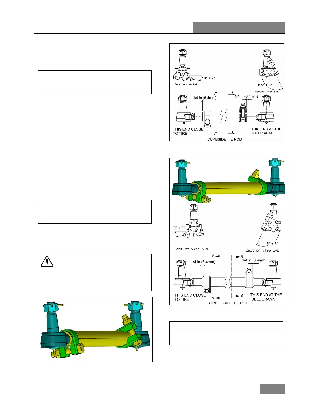
CAUTION
Reinstall tie rod clamp as per FIGURE 17 &
FIGURE 18 as they might interfere with other
components.
FIGURE 17: CURBSIDE TIE ROD - CLAMPS POSITION
16199
FIGURE 18: STREET SIDE TIE ROD - CLAMPS POSITION
16200
If tie rod is not properly aligned with stud,
binding will result.
4.8 STEERING ARMS
The left and right wheel steering arms are
secured to a steering knuckle at one end and to
a tie rod at the other end.
 Loading...