SECTION 14: STEERING
14
PA1621 Maintenance Manual All Series | January 2017
8.2 INSTALLATION
1. Route the white horn wire and the 4-pin
connector through the opening on the
steering wheel.
2. Align the mark on the steering wheel hub
with the mark on the spline shaft and slide
the wheel onto the shaft.
3. Tighten steering wheel retaining nut.
TORQUE : 35-45 lb-ft (47-61 Nm)
4. Plug the 4-pin connector and connect the
white horn wire to the center pad.
5. Reinstall the center pad and test for proper
horn functioning.
8.3 CLOCKSPRING REPLACEMENT
1. Remove the steering wheel.
2. Remove the 2 clockspring mounting screws
and then remove the clockspring. You will
have to disconnect the clockspring harness
connector located lower along the steering
wheel column (Figure 14). If necessary,
remove the steering column covers.
3. Route the new clockspring harness through
the opening in the clockspring support
(Figure 14). Plug the connector at the base
of the steering wheel column and fix
harness along the steering wheel column.
FIGURE 14: CLOCKSPRING INSTALLATION
4. Mount the clockspring in place with 2
screws.
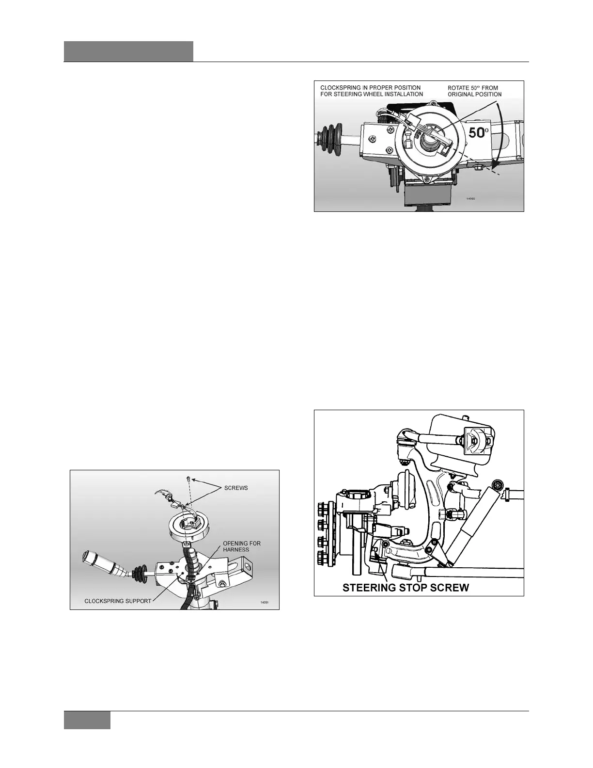
5. Break the paper seal and rotate the center
part of the clockspring about 50° clockwise
(Figure 15). This step is necessary for the
installation of the steering wheel.
FIGURE 15: PROPER CLOCKSPRING POSITION
6. Reinstall the steering wheel.
9. TURNING ANGLE ADJUSTMENT
The maximum turning angle is set through two (2)
steering stop screws installed on the knuckles,
above the ABS wheel sensors. Steering stop
screws are factory adjusted to accommodate the
chassis design, and therefore, do not require
adjustment on new vehicles. However, these
should be checked and adjusted if necessary,
any time a steering system component is
repaired, disassembled or adjusted. Refer to
section 10 "Front Axle" under heading ‘’6.4
‘’Turning Angle Adjusment".
FIGURE 16: STEERING STOP SCREW ON IFS
 Loading...