SECTION 14: STEERING
18
PA1621 Maintenance Manual All Series | January 2017
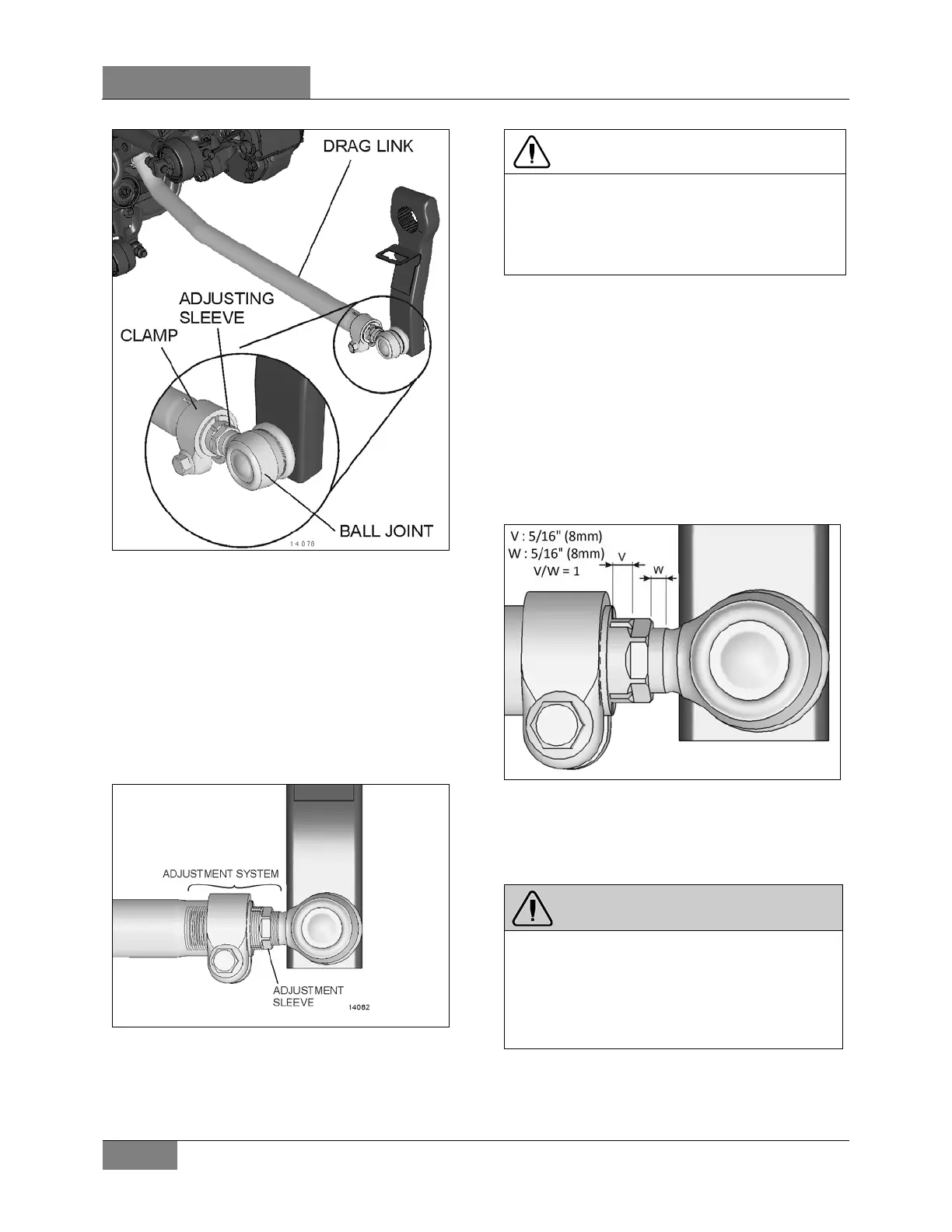
FIGURE 22: DRAG LINK
12.1 FINE ADJUSTMENT
The drag link fore end is provided with an
adjusting sleeve which has internal and external
left and right threads. Turning this sleeve allows
fine adjustments to the length of the draglink.
Apply a small amount anti-seize compound on
the threads for corrosion protection. Be sure to
avoid smearing the ball joint boot.
FIGURE 23: DRAG LINK ADJUSTMENT SYSTEM
CAUTION
Too little pressure on the clamp can destroy the
threaded adjustment system sleeve.
Apply the recommended torque for clamp nut.
TORQUE: 118-133 lb-ft (160-180 Nm)
Fine adjustment of the drag link length should
be performed exclusively by turning the adjuster
sleeve.
12.1.1 Adjustment System Thread Lengths
When assembling the adjuster sleeve or ball
joint, be sure to assemble the parts within the
following prescribed thread lengths and values.
Lengths V and W should be measured prior to
removal to restore the steering system to its
original state.
FIGURE 24: DRAG LINK ADJUSTMENT SYSTEM
Dimension V and W should be equal: V/W = 1
Dimension V: 5/16″ (8mm)
Dimension W: 5/16″ (8mm)
WARNING
To preserve the integrity of the adjusting
system, length V and W should never exceed
5/8″(16mm) ± 1 thread pitch.
Length V and W should be equal within ±
1mm
 Loading...