SECTION 14: STEERING
PA1621 Maintenance Manual All Series | January 2017
17
the rod end. Install washers. Tighten nut and
install a new cotter pin. Depending on axle
type, select the appropriate torque,
IFS, TORQUE: 245-270 lb-ft (332-366 Nm)
I-BEAM, TORQUE: 165-236 lb-ft (224-320 Nm)
CAUTION
Input shaft marks must be aligned before
adjusting pitman arm.
11.3 ADJUSTMENT
1. Disconnect the drag link from pitman arm.
Center steering wheel by dividing the total
number of steering wheel turns in two. Scribe
a reference mark on steering gearbox at the
center previously determined.
2. Using a protractor, check the angle of the
pitman arm (refer to Figure 18 & Figure 19
for details).
3. The pitman arm should be adjusted with
reference marks aligned or to an angle of 2.5º
towards front of vehicle (I-Beam axle) or 0°
(Independent Front Suspension) in relation
with the vertical axis. If not, unscrew and
remove fixing nut. Remove the pitman arm
according to the procedure outlined under
previous heading "Pitman arm removal".
Adjust to the proper angle.
4. When adjustment is achieved, replace fixing
nut and tighten
TORQUE: 470-570 lb-ft (637-773 Nm)
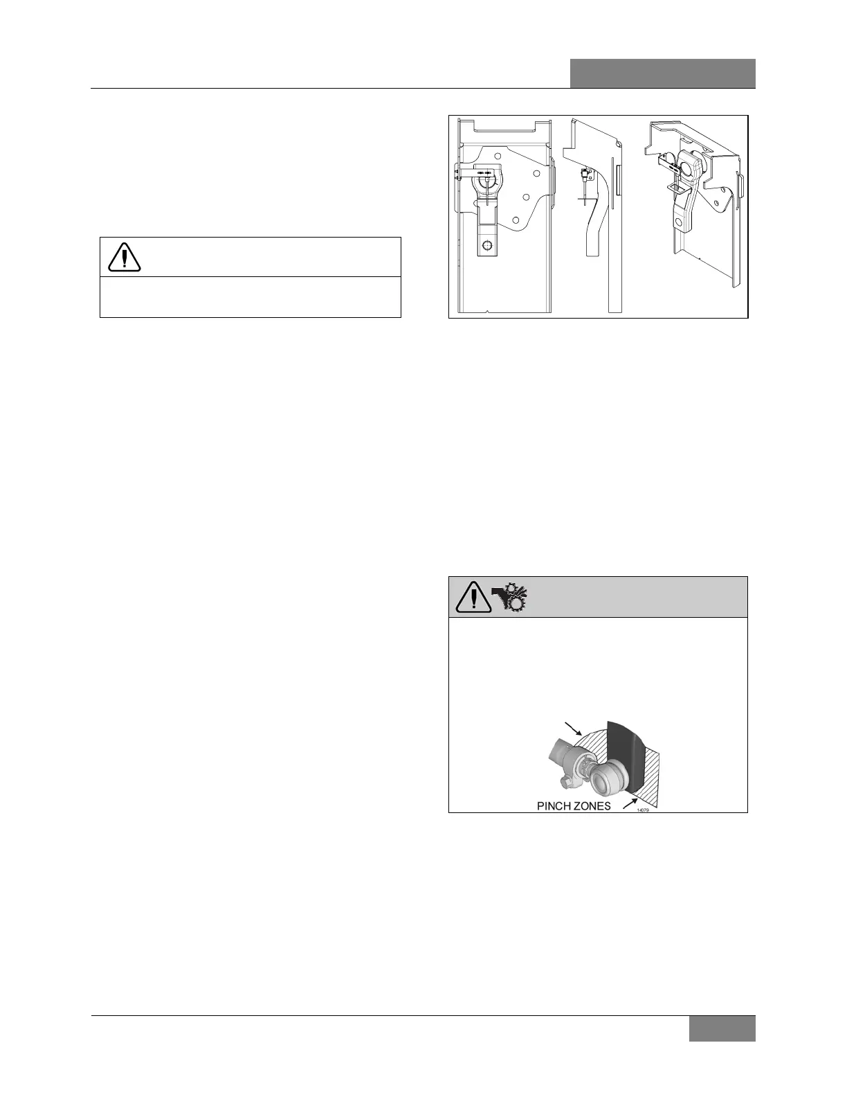
11.4 TAG AXLE UNLOADING SWITCH
ADJUSTMENT (OPTIONAL)
1. Make sure vehicle wheels are straight and
facing forward.
2. Line up switch lever with reference to the
bracket center (Refer to Figure 21).
FIGURE 21: TAG AXLE UNLOADING SWITCH
ADJUSTMENT
14061
12. DRAG LINK (I-BEAM AXLE)
The draglink on your vehicle connects the
steering gear pitman arm to the front axle’s
steering arm.
For additional details please refer to ZF
assembly instructions LMN404-3 and Lemförder
service information leaflet for the fine adjustment
system.
PINCH HAZARD
Keep hands and fingers clear of pinch zones
around pitman arm.
Pinch zones are between pitman arm and
clamp, and between front of pitman arm and
vehicle structure.
 Loading...