SECTION 11: REAR AXLES
PA1621 Maintenance Manual All Series | January 2017
9
remember to replace them afterwards.
7. Disconnect the brake chamber hoses.
NOTE
Position the hoses so they will not be damaged
when removing the axle.
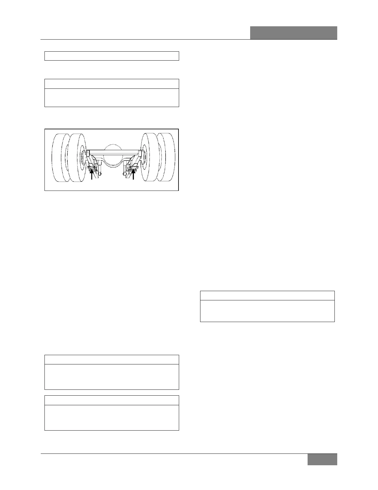
8. Install jacks under the axle jacking points to
support the axle weight (refer to Figure 6).
FIGURE 6: JACKING POINTS ON DRIVE AXLE H3B762
9. Remove the four shock absorbers as
outlined in Section 16: Suspension under
heading Shock Absorber Removal.
10. Remove the sway bar.
11. Remove the lower and upper longitudinal
radius rod supports from vehicle sub-frame
as outlined in Section 16: Suspension,
under heading "Radius Rod Removal".
12. Remove the transversal radius rod support
from the vehicle sub-frame.
13. Remove the two retaining nuts from each of
the four air bellows lower mounting
supports.
14. Use the jacks to lower axle. Carefully pull
away the jacks axle assembly from
underneath vehicle.
15. Reverse removal procedure to reinstall drive
axle.
NOTE
Refer to Section 16: Suspension for
suspension components proper tightening
torques.
NOTE
Refer to section 13 "Wheels, Hubs And Tires"
for correct wheel bearing adjustment
procedure.
2.5 DISASSEMBLY AND REASSEMBLY
Disassembly and re-assembly procedures are
covered under applicable headings in Meritor's
"MAINTENANCE MANUAL, NO. 5A", found on
your Technical Publications USB flash drive.
2.6 GEAR SET IDENTIFICATION
Gear set identification is covered under
applicable heading in Meritor's "MAINTENANCE
MANUAL NO. 5A", found on your Technical
Publications USB flash drive.
2.7 ADJUSTMENTS
Adjustments are covered under applicable
headings in Meritor's "MAINTENANCE MANUAL
NO. 5A", found on your Technical Publications
USB flash drive.
2.8 FASTENER TORQUE CHART
A differential fastener torque chart is provided in
Meritor's "MAINTENANCE MANUAL NO. 5",
found on your Technical Publications USB flash
drive.
2.9 TIRE MATCHING
Drive axle tire matching is covered under the
applicable heading in Section 13, "Wheels, Hubs
And Tires" in this manual.
2.10 DRIVE AXLE ALIGNMENT
NOTE
For drive axle alignment specifications, refer
to paragraph 2.10.2 ‘’ Drive Axle Alignment
Specifications’’ in this section.
The drive axle alignment consists in aligning the
axle according to the frame. The axle must be
perpendicular to the frame. The alignment is
achieved with the use of shims inserted between
the lower longitudinal radius rod supports and
the frame.
Drive axle alignment is factory set and is not
subject to any change, except if the vehicle has
been damaged by an accident or if there are
requirements for replacement.
If the axle has been removed for repairs or
servicing and if all the parts are reinstalled
exactly in the same place, the axle alignment is
not necessary. However, if the suspension
supports have been replaced or altered,
proceed with the following instructions to verify
or adjust the drive axle alignment.
 Loading...