SECTION 06B: X3 SERIES ELECTRICAL
PA1621 Maintenance Manual All Series | Jul 2017
73
1. Unscrew both “Phillips” light screws, and
then remove the light assembly.
2. Position the new light assembly and install
the “Phillips” screws.
11.4.1 Clearance and Identification Light
Removal and Replacement
The clearance and identification light are sealed
units (LED) and can be replaced in accordance
with the following procedure:
1. Unscrew both “Phillips” light screws, and
then remove the light assembly.
2. Position the new light assembly, and then
install the “Phillips” screws.
11.5 FOG LIGHTS
Optional halogen fog lights can be mounted on
this vehicle to give the driver better visibility in
foggy weather, or to improve the range of vision
just ahead of the coach.
11.5.1 Bulb Removal and Replacement
1. Pull on the release handle located in the front
service compartment, near the door lower
hinge. The bumper will lower gradually.
2. Unscrew the wing nut and pivot assembly
upwards.
3. Unscrew the outer ring. Disconnect the light
unit connection and remove the bulb.
4. Install the new bulb, reconnect the light unit
and replace in its proper position.
CAUTION
During this step, avoid contacting the bulb
with your fingers. This could alter the bulb life.
5. Reinstall the outer ring, pivot the assembly
downwards.
6. Fasten the wing nut and securely close the
bumper.
12. X3 SERIES INTERIOR LIGHTING
EQUIPMENT
12.1 CONTROL PANEL LIGHTING
The instrument gauges and switches mounted
on all control panels are energized whenever the
exterior light switch is pushed to the first
position. A control dimmer located on the
dashboard is used to vary the brightness of the
panel gauges, switches and indicator lights.
The gauge lights, panel lights, switch lights and
indicator lights have a different bulb
arrangement. Thus, the procedure to change a
defective bulb can vary according to the
application.
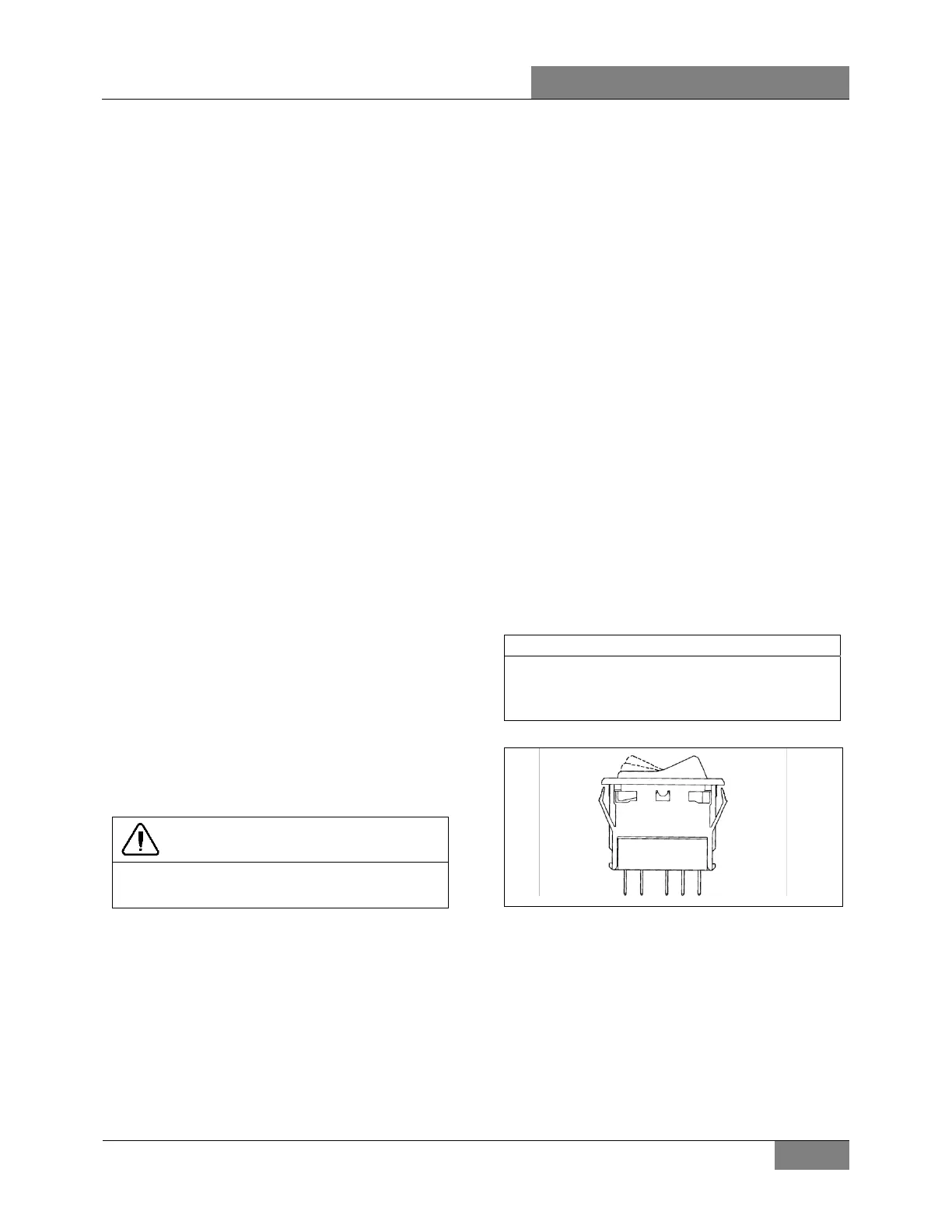
12.1.1 Switch Lighting
1. Slightly pull the switch with a defective LED
away from the control panel.
2. Disconnect the electric cable from the
switch.
3. To install a new switch, reverse the
procedure (Figure 61)
NOTE
Switches are lighted by the use of LED. When
lighting on a switch fails, replace defective
switch as a unit.
06321
FIGURE 61: SWITCH
12.1.2 Telltale Light Replacement
Telltale module is non-serviceable and must be
replaced as a unit.
1. Unscrew and remove the top dashboard
panel.
2. Remove the telltale back wire electric
connectors.
 Loading...