SECTION 14: STEERING
26
PA1621 Maintenance Manual All Series | January 2017
2. Thoroughly grease rubbing pad and ball pin
with Shell Retinax LX or equivalent.
3. Insert ball pin into body.
4. Insert thrust cap, compression spring and
adjuster piece into body.
5. Tighten adjuster piece fully home (SOLID)
locating thrust cup onto ball pin.
6. Still with tool located on adjuster piece, back
off carefully (LEAST AMOUNT) until
adjuster piece split pin is allowed to pass
through body, and that ball pin shank can be
moved by moved of hand, then remove tool.
NOTE: If ball pin does not rotate when re-
adjusted in line with above instructions, this
suggests that ball pin has local worn flats. In this
instance ball pin, thrust cup and rubbing pad
MUST be replaced, if not FAILURE could occur
in service, i.e. ball pin not being able to move in
assembly when turning from lock to lock.
7. Fit cover plate into top of ball joint body, re-
peen using a cold chisel to secure.
8. Screw assembled ball joint onto tie rod.
Lining up marks on both body and tie rod
previously made, or retracking using manual
instructions.
9. Fit pinch bolts and nuts then tighten nuts
alternately and progressively thus securing
ball joint to tie rod.
TORQUE: 85-103 lb-ft (115-140 Nm)
10. Fit dirt seal (pressing) and dirt seal (rubber)
onto ball pin.
11. Locate ball joint and tie rod assembly with
lever, carefully align and fit ball pin into hole
in tie rod arm.
NOTE: Ball pin and ball pin tapers in bottom tie
rod arms must be clean, dry and free from oil
prior to assembly.
12. Fit pin washer onto ball pin.
13. Screw pin nut onto ball pin then tighten.
TORQUE:175-200 lb-ft (237-271 Nm)
14. Using a 2lb hammer, tap tie rod arm to
"shock' ball pin into taper hole.
15. Re-torque pin nut
TORQUE:175-200 lb-ft (237-271 Nm)
16. Fit split pin, if slot/hole are not in line, adjust
up to next slot.
17. Re-charge ball joint with Shell “Retinax LX”
or equivalent grease through grease fitting.
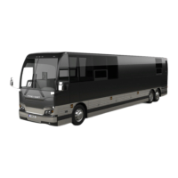
13.10 STRAIGHT BODY TYPE BALL JOINT
FIGURE 31: STRAIGHT BODY TYPE BALL JOINT
13.10.1 Visual Inspection
Visually inspect for missing or damages
grease fittings and replace if required.
Damaged sealing boot or improper sealing
requires seal replacement.
Check ball joint connection for missing
cotter pins.
Check for looseness in the ball/socket
assembly.
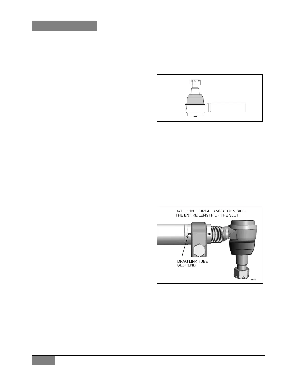
FIGURE 32: ADEQUATE CLAMPING CONDITION
For adequate clamping, the ball joint threads
must be visible the entire length of the tube slot.
If not, the drag link must be adjusted or
replaced. It is either the wrong size, or improper
adjustment was used to compensate for another
problem (e.g. bent steering arm).
 Loading...