SECTION 06A: H3 SERIES ELECTRICAL
PA1621 Maintenance Manual All Series | January 2017
29
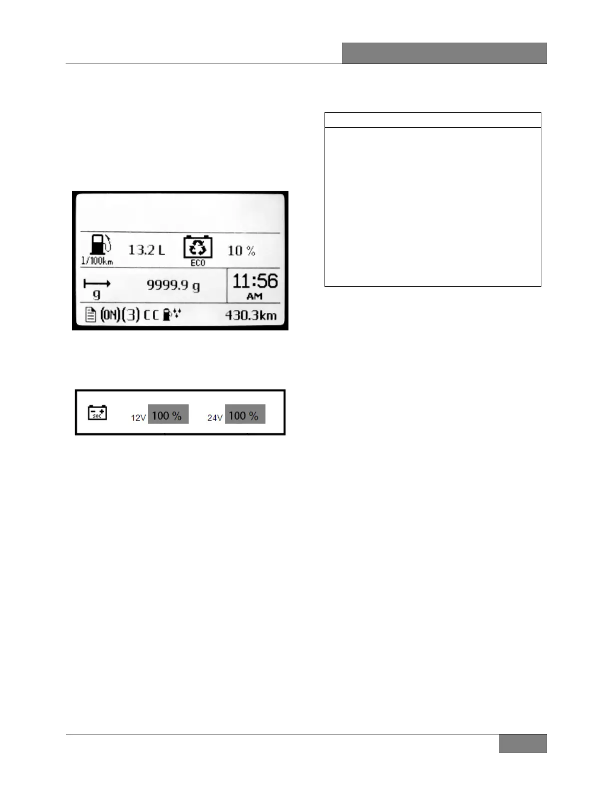
5.3 DID DISPLAY
In the DID you will find the percentage of trip
made with regenerated electricity displayed
along with the instantaneous fuel consumption.
This value is reset each time the engine is
restarted.
FIGURE 17: PRIME DID DISPLAY
In addition to the standard voltage gage, the DID
also includes a state of charge gage for the
batteries:
FIGURE 18: BATTERY STATE OF CHARGE
This gage displays the level of charge for the
12V and 24V battery banks in percentage.
6. TROUBLESHOOTING AND TESTING THE
MULTIPLEX VEHICLES
6.1 PROBING VOLTAGE ON THE
MULTIPLEX CIRCUITS
Some Multiplex modules are supplied by 12
volts while others are supplied by 24 volts. The
12-volt or 24-volt information is found on the
modules symbol in the wiring diagram. Before
taking voltage readings to track the source of a
problem, first verify if the module is supplied by
12V or 24V, if not, residual voltage on the
module inputs/outputs can draw an erroneous
conclusion.
Inactive Multiplex output = Residual voltage of
18% to 33% of supply voltage.
Inactive Multiplex input = Residual voltage of
50% of supply voltage.
NOTE
o Verify on the wiring diagram whether the
voltage is 12V or 24V,
o For a 12V module: an active voltage would
be 12V or 0V but not in between. If you
measure the intermediate tensions (ex.
6V, 2V, or 4V) this must be interpreted as
if the input or the output is inactive.
o For a 24V module: an active voltage would
be 24V or 0V but not in between. If you
measure the intermediate tensions (ex.
12V, 4V, or 8V) this must be interpreted as
if the input or the output is inactive.
6.2 CAN NETWORK
The CAN network wiring is separated in sections
and uses connectors that are not shared with
other circuits. This allows sections of the
network to be isolated to help locate short-circuit
on the CAN.
In case of short-circuit on a section of the CAN
network, this affects all the modules on that
section and they all act as “No response” in the
error messages of the “ELECTRICAL SYSTEM”
menu.
To locate a short-circuit, proceed by
disconnecting one module zone at a time while
verifying if this makes inactive the errors in the
modules still connected. Connector C1 (front
electrical & service compartment) disconnects
all the modules located at the rear of the vehicle
and isolate them from the network. Connector
C5 (front electrical & service compartment)
disconnects and isolate all the modules from the
entrance door & wiper control panel. Connector
C3 (rear electrical panel) disconnects all the
modules at the rear of the vehicle and isolate
them from the network.
Example: Disconnect C5 and C1 and then verify the
status of the errors. If the front modules (A41 to A46)
now give inactive errors, which means short-circuit is
elsewhere than in the front electrical & service
compartment.
 Loading...