SECTION 22: HEATING AND AIR CONDITIONING
52
PA1621 Maintenance Manual All Series | Section Revised November 2017
air conditioning unit permits a wider temperature
range in the passenger’s area.
6.4 HEATING
The schematic of FIGURE 3 shows the central
HVAC system heating arrangement.
On coaches, in addition to the normal heating
provided by the engine, an optional preheating
system (104,000 Btu/hr) may have been
installed above the rear wheelhousing on the
L.H. side.
6.4.1 Driver’s Unit Hot Water Pneumatic
Valve
The flow of hot water to the driver's unit heater
core is controlled by a normally-open (NO)
pneumatic valve like. The valve, located at the
ceiling of the spare wheel compartment
(Figure 66), is designed so that the pilot solenoid
valve, which is part of the assembly, opens and
closes a port which directs air pressure to the
actuator casing, thereby opening or closing the
valve.
When the vehicle is operating without electrical
supply to the pilot solenoid valve, no air
pressure is admitted to the actuator casing, the
cylinder spring pushes up against the cylinder,
thereby keeping the water valve open.
Air pressure at port + 24-V signal at coil =
valve closed
The driver’s unit hot water valve requires a
minimum amount of maintenance. The valve
should be free of dirt sediment that might
interfere with its operation. No other
maintenance is needed unless a malfunction
occurs.
FIGURE 66: DRIVER'S UNIT HOT WATER PNEUMATIC
VALVE ASSEMBLY
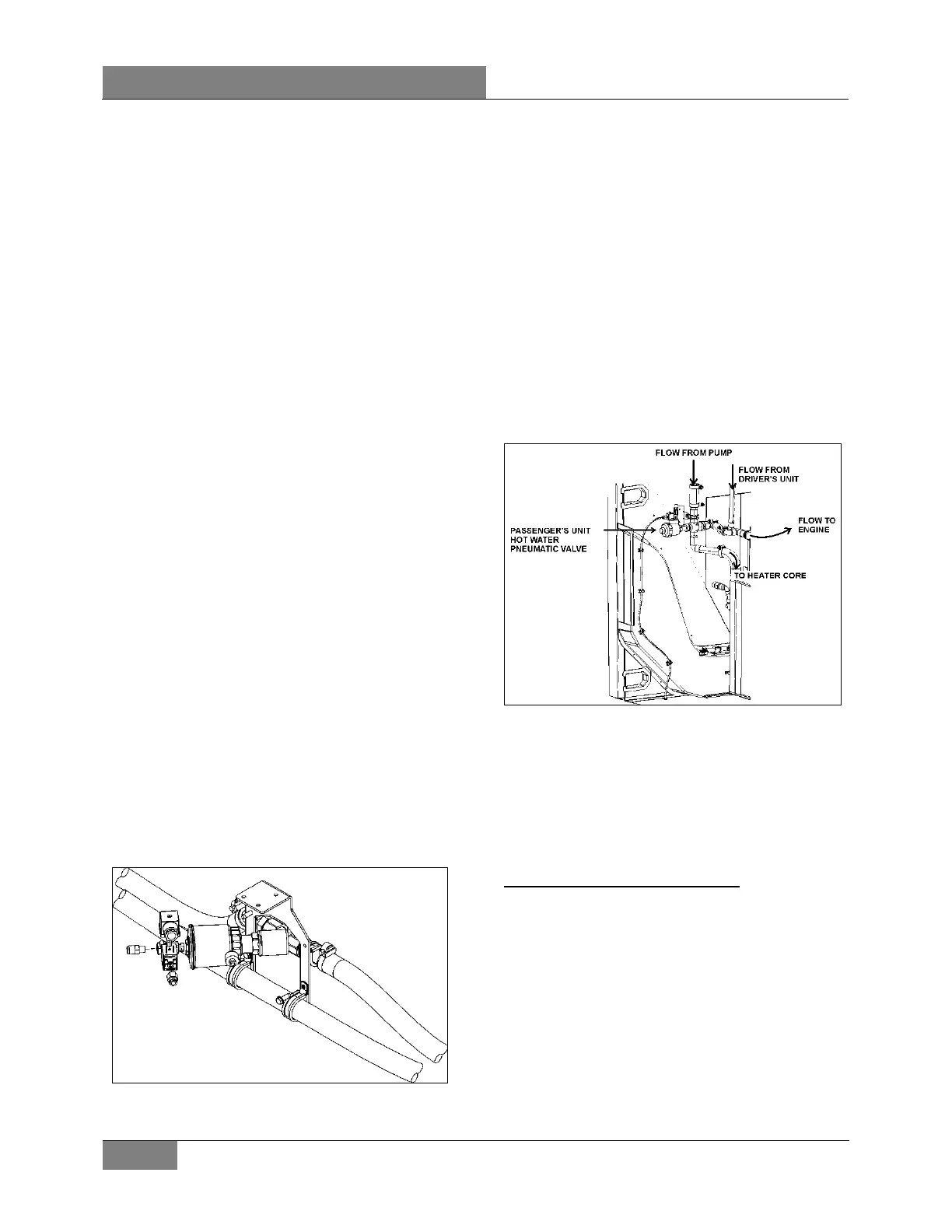
6.4.2 Passenger’s Unit Hot Water Pneumatic
Valve
The flow of hot water to the vehicle’s central
heater core is controlled by a normally-open NO
3-way pneumatic water valve assembly (Figure
67). The valve, located in the evaporator
compartment, is designed so that the pilot
solenoid valve, which is part of the assembly,
opens and closes a port which directs air
pressure to the actuator casing, thereby opening
or closing the valve.
When the vehicle is operating without electrical
power to the pilot solenoid valve, no air pressure
is admitted to the actuator casing, the cylinder
spring pushes up against the cylinder, thereby
keeping the water valve open.
FIGURE 67: PASSENGER’S UNIT PNEUMATIC HOT
WATER VALVE ASSEMBLY
22240
6.4.3 Draining Heating System
To drain the entire system, refer to SECTION 05
COOLING SYSTEM. If only the driver’s unit
heater core or passenger’s unit heater core must
be drained, refer to the following instructions.
Draining Driver’s Unit Heater Core
1. Stop engine and allow engine coolant to cool.
2. Locate the normally open hot water
pneumatic valve on the ceiling of the spare
wheel compartment (Figure 66), disconnect
its wiring connector, and then connect a 24-
volt external power source, using jumper
cables, to close valve.
3. Close the hot water lines shut-off valves
located next the engine on street side (see
Figure 72 or Figure 73).
 Loading...