PA1621 Maintenance Manual All Series | January 2017
Idler arm: Remove cotter pins and nuts from
ball studs connecting relay rod, tie rod and
hydraulic power cylinder to idler arm. Separate
socket assemblies from idler arm.
Remove nuts from bolts attaching bell crank or
idler arm mounting spindle to vehicle subframe.
Remove bell crank or idler arm mounting
spindle.
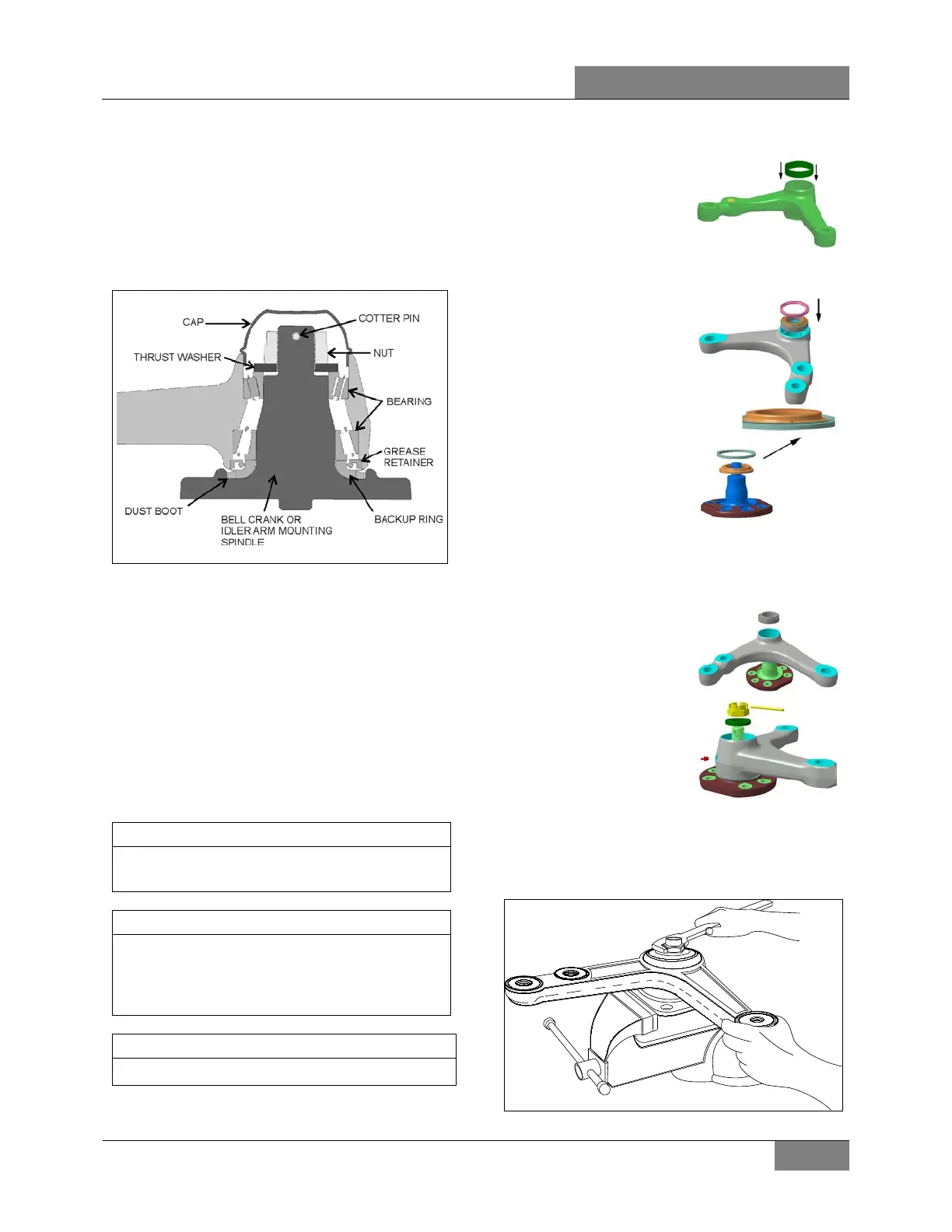
FIGURE 14: BELL CRANK OR IDLER ARM HUB
4.5.2 Bell crank or Idler Arm Hub Disassembly
1. Remove adjacent link assemblies from bell
crank or idler arm as previously described.
2. Remove the cap (Figure 14).
3. Remove the cotter pin, nut and thrust
washer. Remove bearings, grease retainer,
backup ring and the bell crank or idler arm
from its mounting spindle (Figure 14).
4.5.3 Bell Crank or Idler Arm Hub Reassembly
For bearing installation use tool Prevost #
110684.
Install grease retainer according to Figure 14.
Grease must be able to exit the bell crank or
idler arm mechanism. For grease retainer
installation use tool Prevost # 110683.
Apply grease on bearings before installation.
1. Clean parts thoroughly with degreaser.
2.
bearing o
uter race
into appropriate
bore (done on a
3.
Insert the large bearing outer race into
appropriate bore (done on a press).
4.
bearing into outer
race and then, add
grease retainer.
5.
Apply good quality
lithium grease
(#680752) on
backup ring and
dust boot.
6. Install backup ring and dust boot on bell
crank or idler arm spindle.
7.
Apply a thin layer of grease on spindle
shaft.
8. Install bell crank or
mounting spindle,
while holding the
bell crank or idler
arm, slide on the
small bearing
assembly, thrust
washer and secure
using nut.
9. Tighten nut.
TORQUE:130 lb-ft (176 Nm)
10. Rotate assembly 3 turns in each direction.
FIGURE 15: BELL CRANK 16044
 Loading...