SECTION 18a: H3 SERIES BODY
30 PA1621 Maintenance Manual All Series | January 2017
10.5 DEPTH ADJUSTMENT
1. Turn the emergency exit valve to the
“UNLOCK” position.
2. Remove the screws and the plastic molding
covering each of the hinges.
NOTE
Ask an assistant to help you to perform the
following adjustments.
3. Remove the Allen button head screw and
the washer retaining the ball and socket rod
to the upper hinge. See Figure 26.
4. Loosen the vertical bolts on the hinges for
the front section, and for the rear section,
move the central door catch on the door
frame.
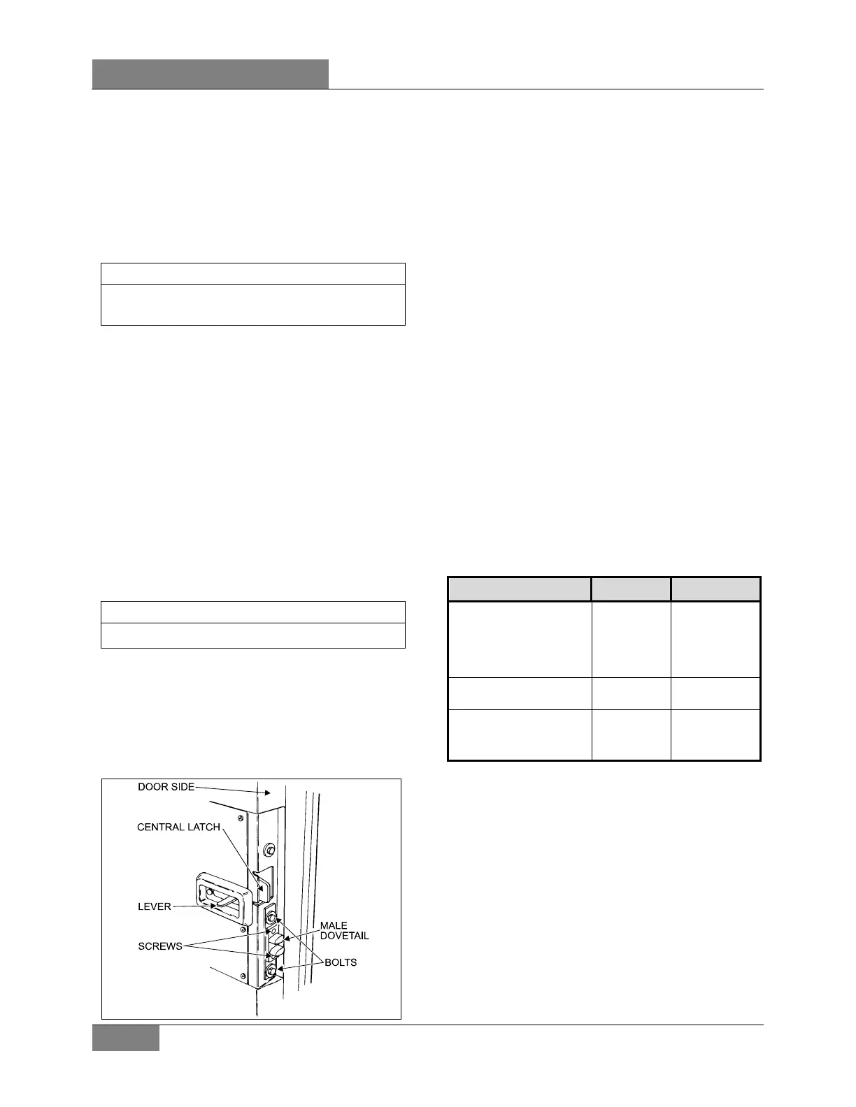
5. To adjust the male dovetail on L.H. side of
the door, remove the two screws and loosen
the two bolts. Slide the male dovetail toward
the interior and loosely tighten the two bolts.
Close the door slowly but firmly, then slowly
open it and tighten the two bolts. Attach
dovetail to the door with screws. See Figure
28.
NOTE
The frame dovetail is not adjustable.
6. Pull and fasten the rod end to the hinge with
the washer and the button screw.
7. Using the screws, attach the plastic
moldings covering the hinges.
8. Reset the emergency exit valve to the
normal position.
FIGURE 28: DOOR LATCH (COACH) 18059
10.6 ROD END ADJUSTMENT
1. Turn the emergency exit valve to the
“UNLOCK” position.
2. Remove the screws and the plastic
moldings covering the upper and lower
hinges.
3. Remove the Allen button head screw and
the washer retaining the rod end with
bearing to upper hinge. See Figure 26.
4. Loosen the jam nut locking the door cylinder
rod end. Close the door firmly, adjust the
rod end center hole in order to be 3/16”
(4,5 mm) eccentric toward the left with the
hinge hole center. Tighten the jam nut.
5. Pull and fasten the rod end to the hinge with
the washer and the button screw.
6. Using the screws, attach the plastic
moldings covering the hinges.
7. Reset the emergency exit valve to the
normal position.
10.7 LUBRICATION
Part Lubricant Frequency
Latches
Upper door catch
Door cylinder rod end with
bearing grease fitting
(Figure 28)
Low
temperature
grease
Every six
months
Door locking mechanism White grease
Every six
months
Key hole
Damper pins (Figure 24)
Hinges
Low viscosity
oil
Every six
months
 Loading...