SECTION 22: HEATING AND AIR CONDITIONING
50
PA1621 Maintenance Manual All Series | Section Revised November 2017
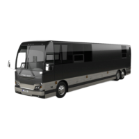
direct air to his knees and/or upper body with
adjustable HVAC air registers and to his feet
with the appropriate button (see FIGURE 62 and
Owner’s or Operator’s manual).
FIGURE 62: DRIVER’S UNIT AIR CIRCULATION
An additional air is located in the stepwell for
step de-icing (Figure 2 & Figure 5). This air flow
is supplied by the passengers’ air ducting
system.
X3 coaches are also equipped with a
defogger/defroster system in the upper
windshield section. Similar system is optional on
H3 coaches.
6.2 AIR CIRCULATION IN PASSENGER’S
AREA
Fresh air enters from the left side of vehicle
through a damper located:
H3 Series - Inside the air intake duct at
the left of the evaporator compartment.
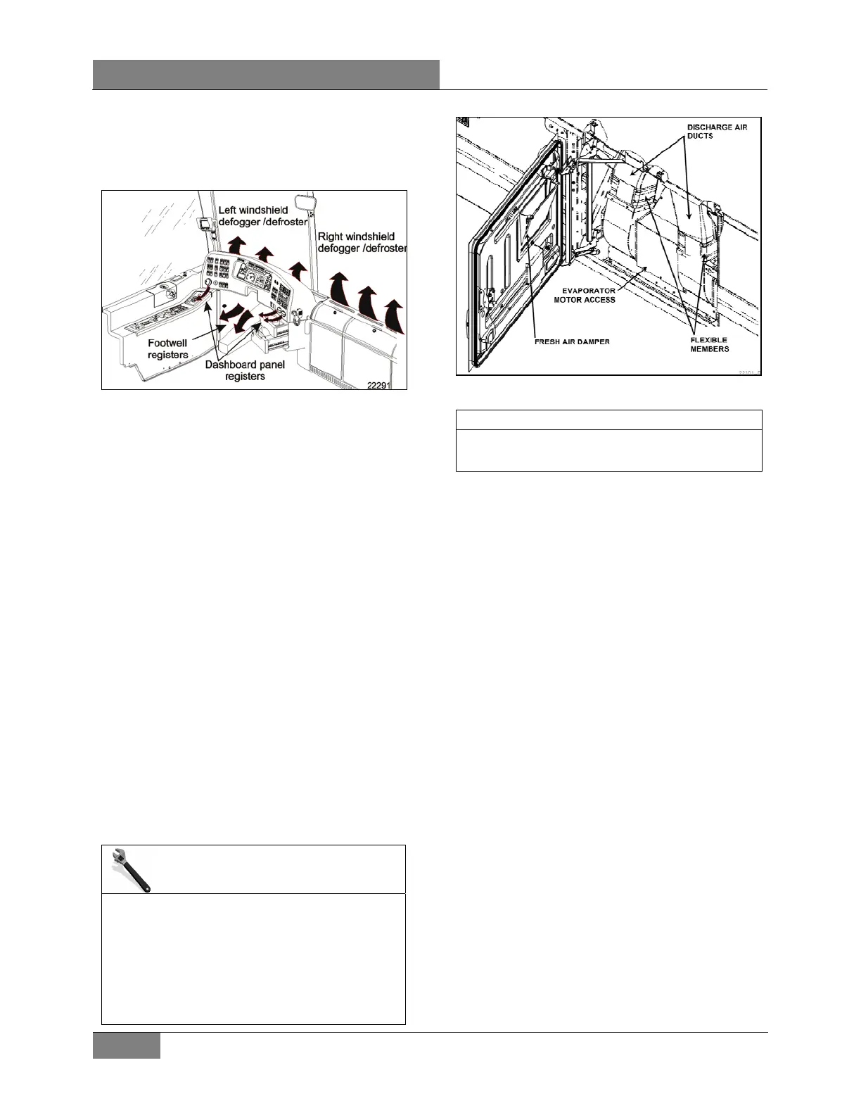
X3 Series - On the evaporator
compartment door (Figure 63).
The damper can be fully opened for normal
operation or partially closed for extreme weather
or highly polluted areas. The recirculation REC
button is located on the HVAC control unit.
Press down the button to partially close the fresh
air damper (refer to the Owner’s or Operator's
Manual for more details).
MAINTENANCE
Passenger’s area fresh air intake filter (X3
Series only)
Clean or replace filter at the intervals specified
by the Lubrication And Servicing Schedule in
Section 24: LUBRICATION & SERVICING.
To clean filter, back flush with water or soapy
water, then dry with air.
FIGURE 63: X3 SERIES PASSENGERS' AREA FRESH
AIR DAMPER
NOTE
Opening the entrance door also partially
closes the fresh air damper.
Return air is drawn through:
H3 coaches - the first entrance step, last
entrance step riser and from the lower
section of the floor ducts in two
locations: one in the rear section of
vehicle and the other in the front section
of vehicle on the L.H. side (Figure 2).
X3 coaches - Return air is drawn from
inside the vehicle through the register
duct located on L.H. side of vehicle
(Figure 5).
A double blower fan unit, which is activated by
the evaporator motor, draws mixed air through
an air filter, cooling and heating coils, then
forces this air in the ventilation ducts (upper
section) along the walls, and finally exhausts it
at the bottom of the windows.
The coaches are equipped with an overhead
compartment ventilation system equipped with
adjustable registers in the passenger’s overhead
console to control air flow. Return air is drawn
just below the middle side windows through an air
filter into the overhead compartment fan;
discharge air is fed to the rotating registers
through the ventilation duct (Figure 64).
The lavatory ventilator found on coaches acts as
the main exhaust for the whole vehicle,
eliminates odors, and finally heats or cools the
lavatory with the vehicle’s ambient air.
 Loading...