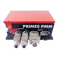
PowerMeasuringModule PMM
35,0(6
23
Revision 13 EN - 02/2023
7.2.2 Pin assignment data connector XF1/XF2
The PMM has two PROFINET
®
interfaces that are connected via an integrated switch. These interfaces are
routed to AIDA-compatible installation sockets with suitable mounting frames.
XF1 is the input (In) and XF2 is the output (Out).
The PMM is connected via Ethernet patch cables of CAT5e quality or higher.
Pin Color coding
Europe T568A
Color coding
Outside Europe T568B
Function
1 Green/White Orange/White TX+
2 Green Orange TX-
3 Orange/White Green/White RX+
6 Orange Green RX-
Tab. 7.4: Pin assignment data connector XF1/XF2
7.2.3 Pin assignment power supply XD1/XD2
The power consumption of the PMM is below 250mA, which is provided by the sensor supply.
Both connectors are internally connected 1:1.
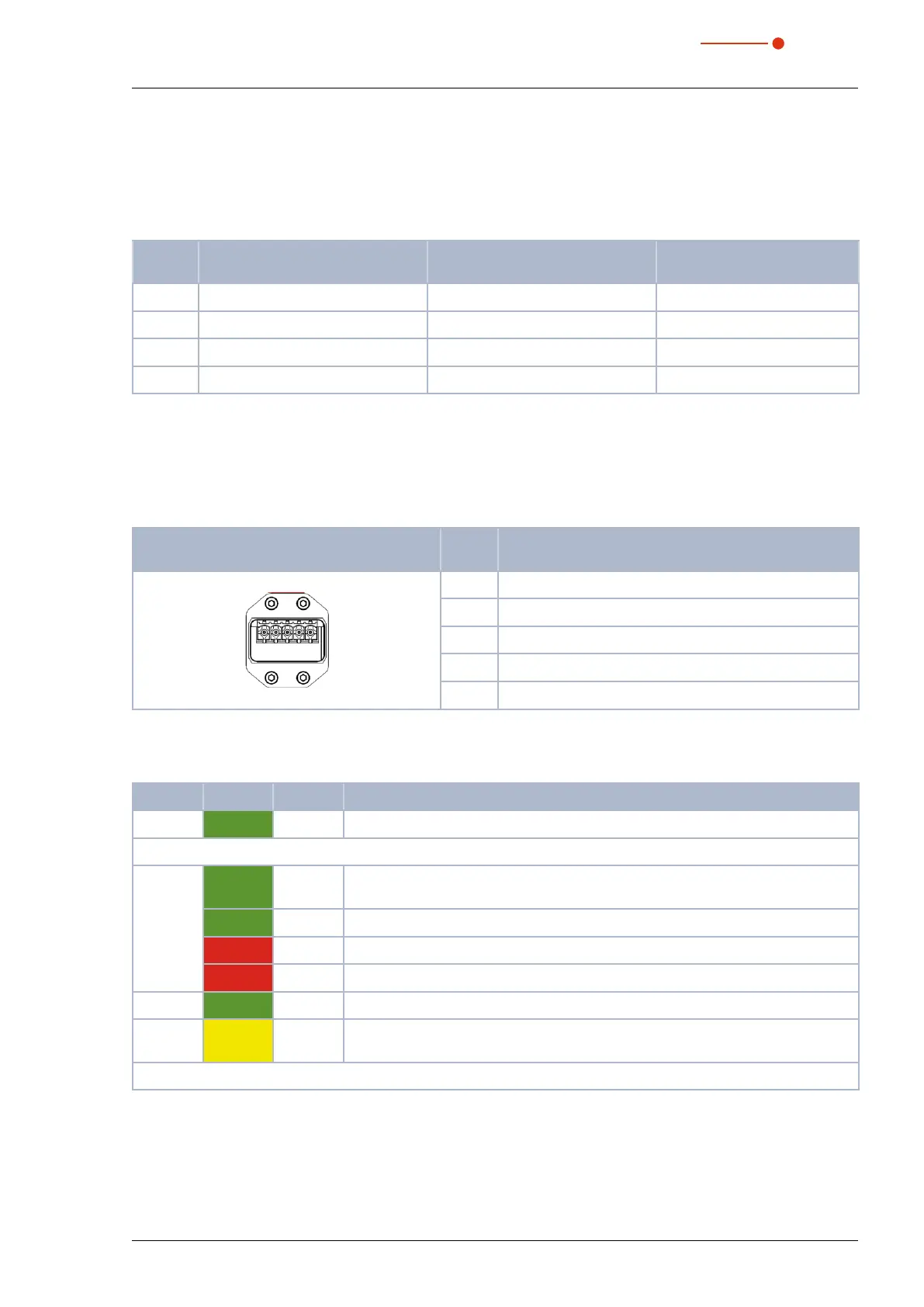
Pin assignment XD1/XD2
(view on connection on the device)
Pin Function
5
1
1 Sensor power supply 24 V
2 GND Sensor power supply
3 Actor power supply 24 V
4 GND Actor power supply
5 FE (functional earth)
Tab. 7.5: Pin assignment power supply XD1/XD2
7.2.4 Status LEDs
LED Color Mode Meaning
Power Green On Supply voltage is connected.
COM Green On Watchdog time-out or „channel, generic or extended diagnostics present“ or
system error.
Green Flashing DCP signal service is triggered via the bus.
Red On No configuration or slow physical connection or no physical connection.
Red Flashing No data exchange.
Link
1)
Green On The device has a connection to the Ethernet (XF1 / XF2).
Tx/Rx
1)
Yellow Flicker-
ing
The device sends / receives Ethernet frames (XF1 / XF2).
1)
without function in the PROFINET
®
fiber optic version
Tab. 7.6: Status LEDs