PowerMeasuringModule PMM
35,0(6
61
Revision 13 EN - 02/2023
13.2 Data model
For the communication of the PMM with the field bus, a specific internal field bus module is used. The PMM
is controlled by a command-byte, which encodes four commands. The PMM data are stored in an “Array of
Byte”, which contains 66 elements. In the table of variables only entries up to byte 56 can be found. The re-
maining bytes contain information which is used for the calibration of the device and is not handled by a user.
PowerMeasuringModule PMM
DeviceNet™
Scanner
Control
CompactLogix
Structured
variables
Array of
byte
Array of double
integer
Communi-
cation modul
Structured
variables
Array of
byte
•
•
•
MaxIrradiation
MaxEnergy
4 Byte
MaxCapacity
4 Byte
Shutter 2 Byte
Status 2 Byte
•
•
•
MaxIrradiation
MaxEnergy
4 Byte
MaxCapacity
4 Byte
Shutter 2 Byte
Status 2 Byte
•
•
•
•
•
•
•
•
1 Byte
1 Byte
1 Byte
1 Byte
1 Byte
1 Byte
1 Byte
1 Byte
1 Byte
1 Byte
1 Byte
1 Byte
1 Byte
1 Byte
•
•
•
•
•
•
•
•
1 Byte
1 Byte
1 Byte
1 Byte
1 Byte
1 Byte
1 Byte
1 Byte
1 Byte
1 Byte
1 Byte
1 Byte
1 Byte
1 Byte
•
•
4 Byte
4 Byte
4 Byte
4 Byte
Adresse0 2 4 8 16
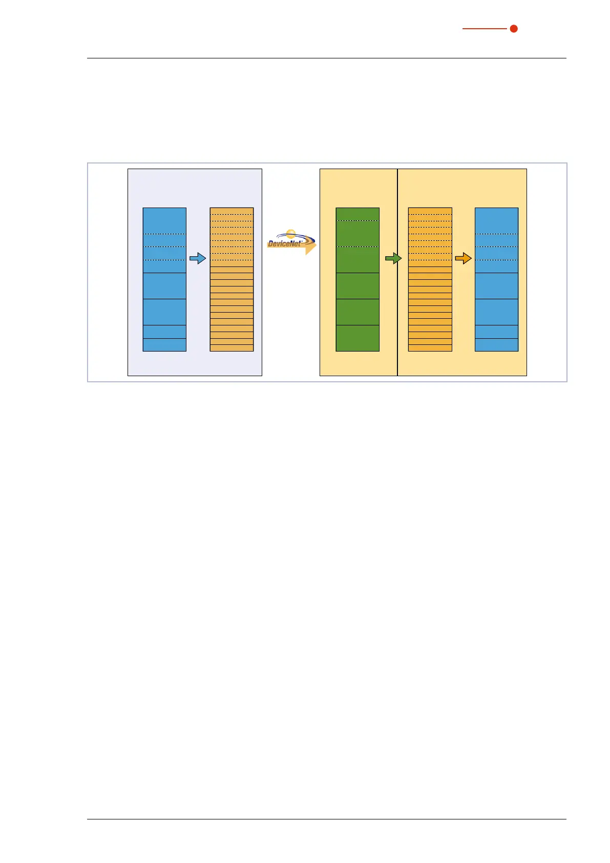
Fig. 13.2: Data structure between PMM and control
The PMM stores the data in the format 2byte Integer and 4byte Integer. With EtherNet/IP™ and
DeviceNet™, the data is arranged in the “Little-Endian” format.
The field bus module used in the PMM generally only supports the “Array of bytes” and no tags, as defined
by the CIP™ (Common Industrial Protocol). The variables of the PMM can therefore not be read directly from
the bus.
13.3 PMM with DeviceNet™
With DeviceNet™, the data is transferred to the control via a scanner module. As an example, the data trans-
fer of a CompactLogix 1769 by Allen Bradley is displayed here.
The measuring data of the PMM is written into the integrated communication module in the form of 2 byte In-
teger and 4 byte Integer. The communication module transfers this data as “Array of Byte” to the bus. Other
data types are not supported.
The scanning module 1769-SDN stores the data as “Array of DINT” (4 byte Integer) in the area “local” of the
control. The control does not contain direct commands which can carry out a type conversion. Therefore, the
data is copied to the target variable in a two-step procedure.
1. Step:
The data range of the type “Array of DINT” is copied to a variable range “Array of Byte” (see Fig. 13.3 on
page62, copy command A). By means of this copying process, data cannot only be copied with the
start addresses modulo 4 (i.e.0,4,8,12,16,20…), but every start address is possible.
2. Step:
The data is copied to the user-defined data types (see Fig. 13.3 on page62, copy command B). The
data is then available within the control.