PowerMeasuringModule PMM
35,0(6
33
Revision 13 EN - 02/2023
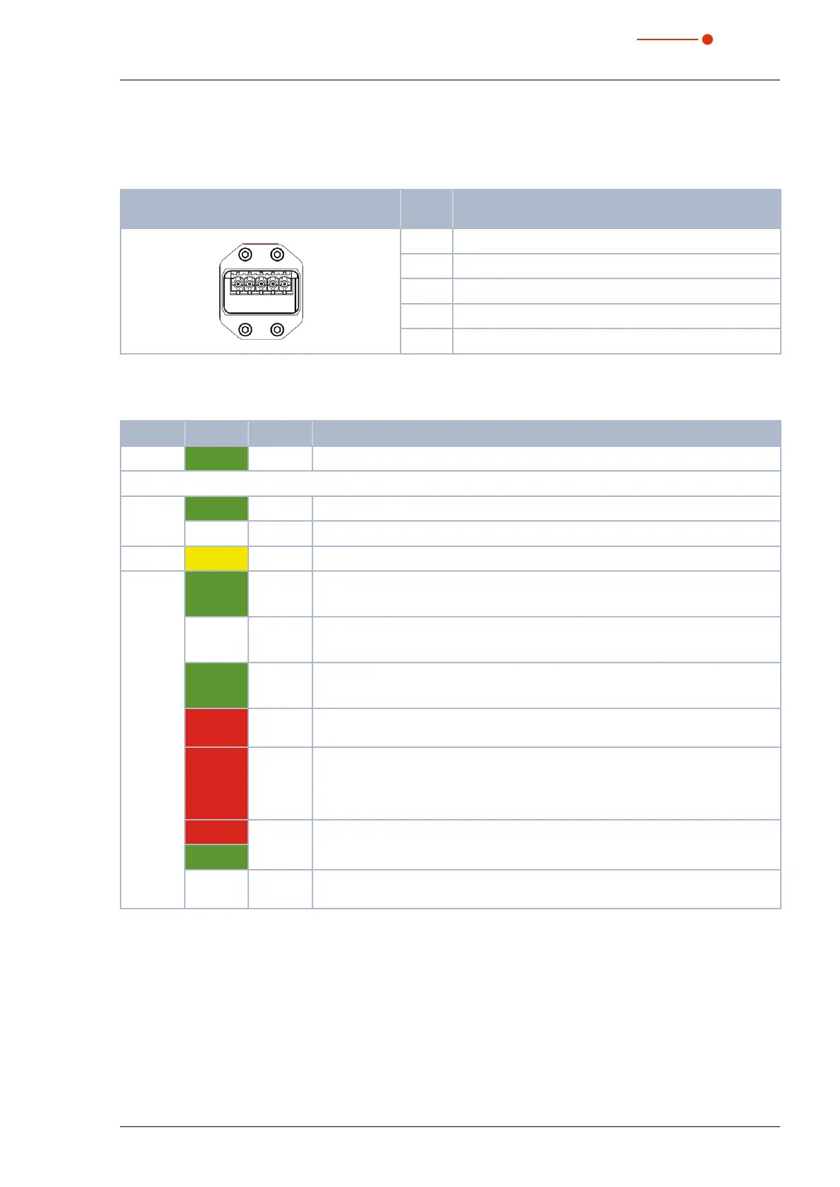
7.6.3 Pin assignment power supply XD1/XD2
The power consumption of the PMM is below 250mA, which is provided by the sensor supply.
Both connectors are internally connected 1:1.
Pin assignment XD1/XD2
(view on connection on the device)
Pin Function
5
1
1 Sensor power supply 24 V
2 GND Sensor power supply
3 Actor power supply 24 V
4 GND Actor power supply
5 FE (functional earth)
Tab. 7.21: Pin assignment power supply XD1/XD2
7.6.4 Status LEDs
LED Color Mode Meaning
Power Green On Supply voltage is connected.
Link Green On Connection established with Ethernet.
Off No connection established with Ethernet.
Tx/Rx Yellow Flashing The device sends/receives Ethernet Frames.
COM Green On PMM, PMM A only – Connected: If the device has at least one connection (includ-
ing the message router).
— Off PMM AP3s only – Connected: If the device has at least one connection (including
the message router).
Green Flashing No connections: If the device has no existing connections but has received an IP
address, the network status display flashes green.
Red On Double IP: If the device realizes that an IP address is already in use, the network
status display glows red.
Red Flashing Time out of the connection: If one or more connections with the device have
reached the time out, the network status display flashes red. This status will not
terminate until all connections, that have timed-out, have been restored or until the
device has been reset.
Red Flashing Self-test: When the device is carrying out a self-test, the network status display
flashes green/red.
Green
— Off Not turned on, no IP address: If the device does not have an IP address (or is
turned off), the network status display is off.
Tab. 7.22: Status LEDs