PowerMeasuringModule PMM
35,0(
28
Revision 13 EN - 02/2023
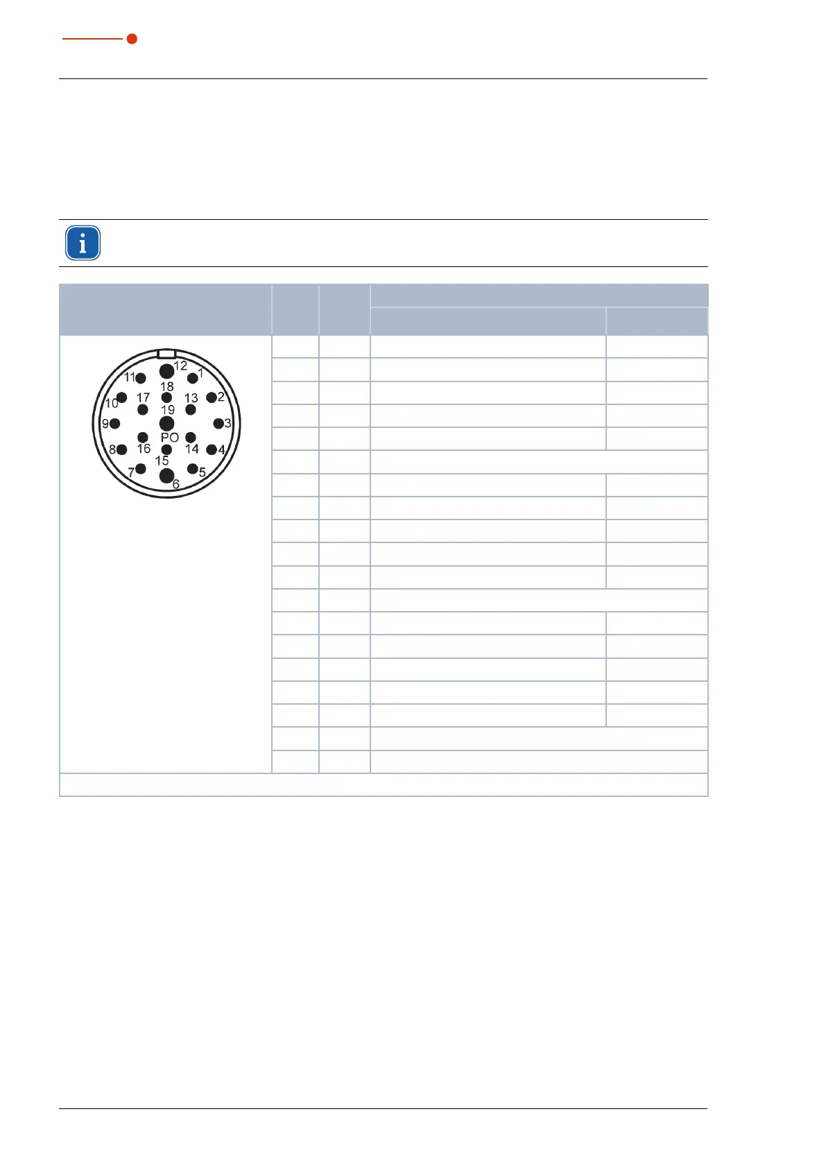
7.4.4 Pin assignment output, 16-Channel XG2Out
The outputs 1 to 17 have two functions, depending on the setting of bit 15:
• In case of bit 15=1 (measurement finished) the 14 lines below are used for displaying the laser power
(Watt) as binary code.
• In case of bit 15=0 those lines provide status information.
After a change of edge of bit 15, the measured value bits should be taken over a few milliseconds
later to avoid runtime problems of the individual bits.
Pin assignment XG2 Out
(view on connection on the de-
vice)
Pin Name Function
Bit15=0 Bit 15=1
male
1 Bit 0 Shutter is open Power Bit 0
2 Bit 1 Shutter is closed Power Bit 1
3 Bit 2 Shutter is moving Power Bit 2
4 Bit 3 Shutter time error Power Bit 3
5 Bit 4 Irradiation time 100 ms Power Bit 4
6 - GND
1)
7 Bit 5 Irradiation time 200 ms Power Bit 5
8 Bit 6 Irradiation time 400 ms Power Bit 6
9 Bit 7 Irradiation time 800 ms Power Bit 7
10 Bit 8 Irradiation time 1,600 ms Power Bit 8
11 Bit 9 Confirmation command closing Power Bit 9
12 - GND
13 Bit 10 Confirmation start measurement Power Bit 10
14 Bit 11 Absorber too warm Power Bit 11
15 Bit 12 System not in operation Power Bit 12
16 Bit 13 Measurement in process, Pulse received Power Bit 13
17 Bit 14 System waiting for pulse Power Bit 14
18 Bit 15 Measurement finished
19 - Supply voltage output driver (24VDC)
1)
Is connected with pin 1 in the power supply (see Tab. 7.12 on page27).
Tab. 7.14: Pin assignment output, 16 channel XG2 Out
The output driver is supplied with 24V via Pin19. The maximum current load of all outputs is 2 Amperes.
A single output can have a load of 500mA. The outputs are not electrically isolated.