PowerMeasuringModule PMM
35,0(6
35
Revision 13 EN - 02/2023
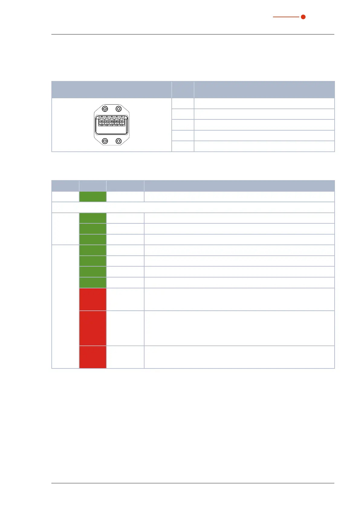
7.7.3 Pin assignment power supply XD1/XD2
The power consumption of the PMM is below 100mA, which is provided by the sensor supply.
Both connectors are connected internally1:1.
Pin assignment XD1/XD2
(view on connection on the device)
Pin Function
5 1
1 Sensor power supply 24 V
2 GND Sensor power supply
3 Actor power supply 24 V
4 GND Actor power supply
5 FE (functional earth)
Tab. 7.25: Pin assignment power supply XD1/XD2
7.7.4 Status LEDs
LED Color Mode Meaning
Power Green On The supply voltage is applied.
L/A Green On There is a connection to the EtherCAT
®
.
Green Flashing The device sends/receives Ethernet frames.
Green Off The device has no connection to the EtherCAT
®
.
Status Green On The device is in OPERATIONAL mode.
1
Green Flashing The device is in PRE-OPERATIONAL mode.
2
Green Simple flash The device is in SAFEOPERATIONAL mode.
3
Green Off The device is in INIT mode.
4
Red Flashing Invalid configuration: General configuration error:
Possible cause: A status change specified by the master isn’t possible, be-
cause of the register or object settings.
Red Simple flash Local error: The slave device application has an EtherCATStats
Changed autonomously.
Possible cause 1: A host watchdog time-out has occurred.
Possible cause 2: Synchronization error, the device switches automatically
after safe operational.
Red Double flash Process data watchdog time-out: A process data watchdog time-out has oc-
curred.
Possible cause: Sync manager watchdog time-out.
Tab. 7.26: Status LEDs
1
Inputs and outputs are valid and the final mode has been achieved.
2
Communication with the application layer already runs through the mailbox, but the process data still isn’t being
communicated. Additional parameters now need to be configured. This includes the mapping of process data and
the setup of the SyncManager and FMMU. The safe operational state can then be queried.
3
Communication of process data will start, but only the input values are valid at the start. Outputs are left in a so-
called safe state. This will change as soon as the master sends valid output values and requests operational state.
4
There is no communication on the application layer, but the master has already accessed the DL information regis-
ter. Here the master at least has to configure the DL address register and channels for the mailbox of the SyncMan-
ager.