PowerMeasuringModule PMM
35,0(
18
Revision 13 EN - 02/2023
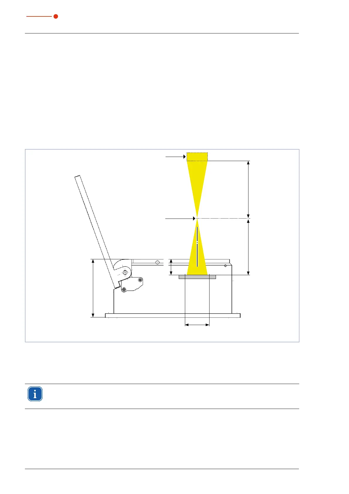
6.2.3 Align the device
The device must be aligned to the laser beam. The laser beam must hit the centre of the inlet aperture.
Please mind and adhere to the specifications and limit values given in chapter17 „Technical data“ on
page88.
Usually, the device is positioned underneath the focusing plane in the beam path (divergent laser radiation). If
this is not feasible, the device can be positioned above the focusing plane.
If the device is mounted above the focusing plane, be aware that the laser radiation is convergent and make
sure that the maximum power density on the absorber will not be exceeded. The absorber is located approx.
25mm below the top edge of the unit when the shutter is open.
The device is aligned with a pilot laser and the reticle on the shutter.
Focusing optics
Focusing plane
25mm
Maximum beam diameter
on the absorber 30mm
88.5mm
Focal width fapprox. Focal width f
Fig. 6.2: Alignment to the laser beam (schematic)
6.2.4 Mount the device
In the bottom of the housing there are four holes Ø 6.6 mm for mounting on a customer-side bracket.
Ensure a good thermal conductivity of the mounting surface, especially for measurement proce-
dures with a high repetition rate (see chapter 8.4 on page40), in order to ensure a fast heat
dissipation.
1. Mount the PMM according to Fig. 6.3 on page19 with 4 screws M6.
The total length of the screws depends on the dimensions of the customer’s bracket.
Screws of strength class 8.8 and a tightening torque of 35N∙m are recommended.