PowerMeasuringModule PMM
35,0(6
25
Revision 13 EN - 02/2023
Pin assignment XF2 Out
(view on connection on the device)
Pin Function
female
2
4
1
5
3
1 5V
2 Signal A
3 ISOGND
4 Signal B
5 Not connected
Tab. 7.8: Pin assignment data connector XF1 In/XF2 Out
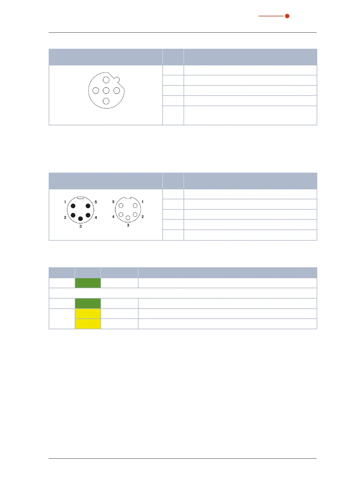
7.3.3 Pin assignment power supply XD1/XD2
The power consumption of the PMM is below 250 mA, which is provided by the sensor supply.
Both connectors are internally connected 1:1.
Pin assignment XD1/XD2
(view on connection on the device)
Pin Function
male female
1 GND Actor
2 GND Sensor
3 FE (functional earth)
4 Sensor supply 24V
5 Actor supply 24 V
Tab. 7.9: Pin assignment power supply XD1/XD2
7.3.4 Status LEDs
LED Color Mode Meaning
Power Green On Supply voltage is connected.
Run Green On Communication with the bus.
Stop Yellow Flashing Device has no physical connection to the bus.
Yellow On A connection exists, but no data will be exchanged.
Tab. 7.10: Status LEDs