3-23
VIBXPERT 11.2010
Options
Max. frequency 10k / time 125ms
SENSOR ANGLE (ORBIT): The angle between the two sensors can be freely
selected between 5° and 175°.
D
ISPLAYED TURNS (ORBIT): The time waveform can be displayed over
multiple rotations* to check the phase stability. When the phase is
stable, the keyphaser mark in the orbit remains constant.
A2. Measurement tasks in the 'Signals' tab
MEASUREMENT QUANTITY: see section A1 - 'Overall values' (prev. page).
F
ILTER TYPE (ENVELOPE): Software / Hardware; envelope calculation
using a software algorithm or via a hardware module.
HP/LP F
ILTER (ENVELOPE)
36-36 kHz; 1-40/ 20/ 10/ 5/ 2,5 kHz (hardware filter)
0.5 / 2.5 / 5 / 10 / 20 / 40 kHz (lowpass (LP) software filter)
Highpass (HP) software filter from 100Hz to TP, freely adjustable
D
EMODULATION FACTOR (ENVELOPE): Ratio of the highpass frequency prior
to demodulation to the lowpass frequency after demodulation.
L
OWER / UPPER FREQUENCY (F
MIN
/ F
MAX
): Lowest and highest frequency
which can appear in the signal. The lower frequency setting of 0.5
Hz or 1 Hz only applies for spectra and overall value measure-
ments. For the 'Displacement' and 'User-defined' measurement
quantities, the DC component in the signal can be recorded
(lower frequency = DC).
For envelope spectra only the ‘upper frequency’ (f
max.
) is specified.
S
AMPLE FREQUENCY (TIMEWAVEFORM): The sample frequency for the time
signal defines the maximum, upper frequency.
M
EASUREMENT TIME (TIMEWAVEFORM): The length of the time window
depends on the sample frequency. The maximum measurement
time is 640 s.
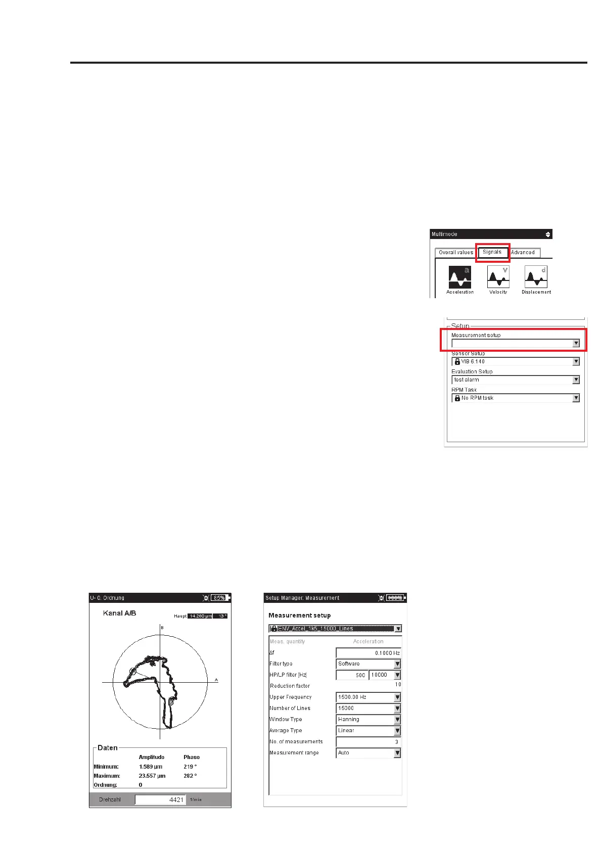
Left:
Keyphaser mark in the orbit re-
mains stable over multiple rota-
tions.
Right:
Setup for envelope spectrum
* up to max. number of averages
 Loading...