PCX SMS AND PCX 256 SYSTEM MANUAL
RINS871-3 Page: 111
14.2 PSTN Wiring
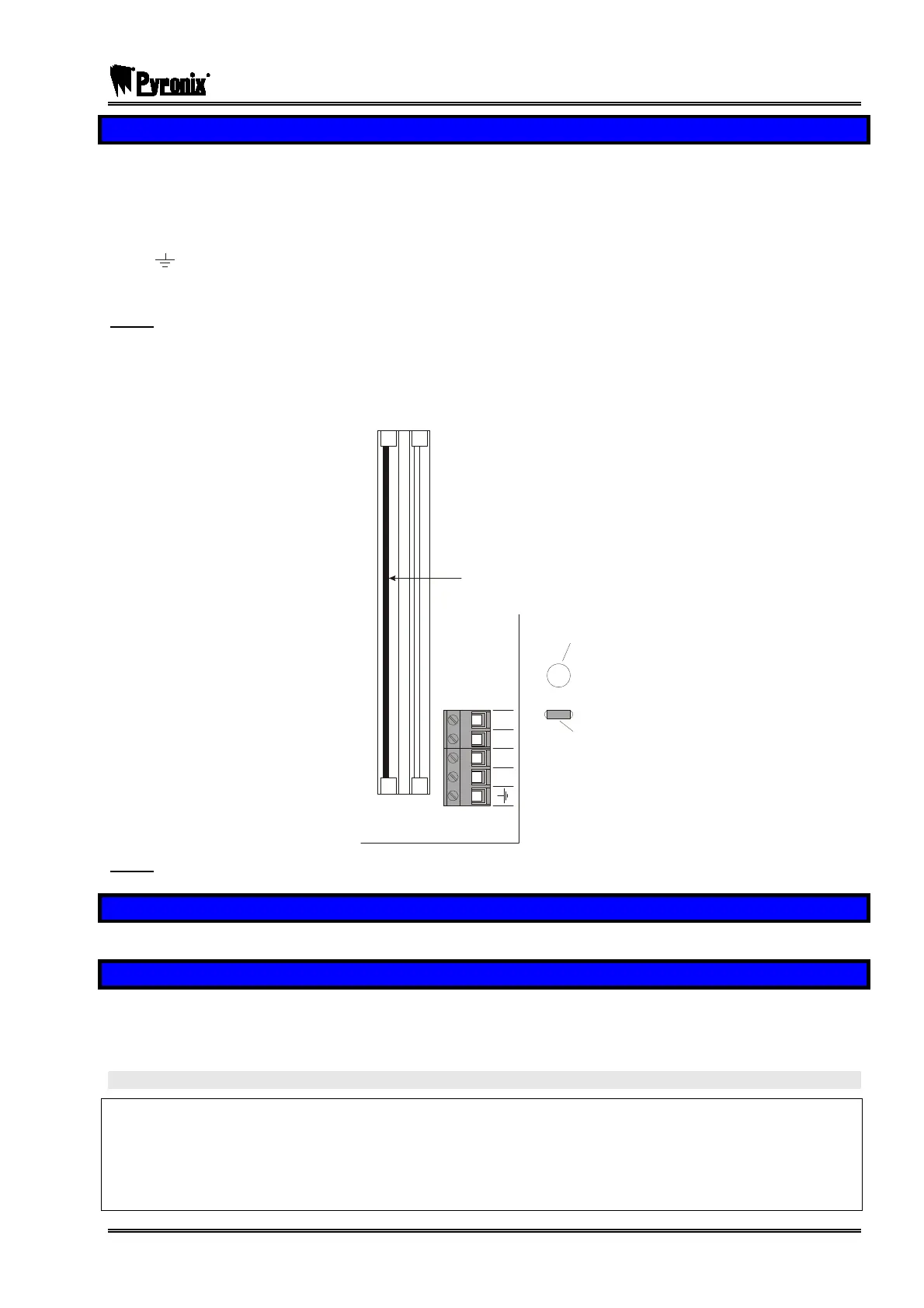
Connections are made to the terminals on the end station PCB:
A Telephone line output for connection to analogue PSTN telephone line
B Telephone line output for connection to analogue PSTN telephone line
A-1 Telephone line output for connection to other telecom equipment
B-1 Telephone line output for connection to other telecom equipment
Telecom ground
Before making these connections, all power must be disconnected from the system.
Note: The Telecom Ground terminal (TE) should ALWAYS be connected to earth in order to
maximise the effectiveness of the transient voltage protection on the unit.
Note that the approvals standard TBR21 clause 4.2 requires to be made via an RJ11 plug and socket.
The cable must be fed into the end station housing through the hole provided, protected by the grommet
supplied, and secured in place with the cable tie, thus:
Grommeted
cable access
Cable tie
Digi-Modem Card
A
B
A1
B1
C
O
M
M
U
N
I
C
A
T
I
O
N
C
A
R
D
E
X
P
A
N
S
I
O
N
C
A
R
D
S
L
O
T
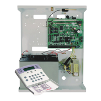
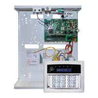
Note: PCB layout varies between PCX models, but labelling and connections are identical.
14.3 Programming the Unit
Programming of all telephone numbers, etc. should be carried out as described on page 97.
14.4 Initialisation
To ensure correct initialisation after installation, wait for the main power to initialise after powering up, then
press the “RESET” button on the end station for approximately 2 seconds.
If this is not done, a “MODEM FAULT” may be indicated.
WARNING
The approval of this product for attachment to the PSTN is void if it is subject to any unauthorised
modification, or if used with, or connected to:
Internal software which has not been approved by BABT.
External control software or control equipment which causes the unit to contravene the requirements of
telecommunications standards.