PCX SMS AND PCX 256 SYSTEM MANUAL
Page: 26 RINS871-3
CHAPTER 7: INSTALLATION
This chapter describes the recommended procedure for installing PCX systems
7.1 Electromagnetic Compatibility (EMC)
The PCX system has been designed to meet or exceed all relevant EMC requirements. This alone does not
guarantee that no problems will be experienced, especially in relation to older equipment not designed to the
same standards, or to equipment for which the same provisions of the EMC Directive do not apply.
To maintain full EMC performance for the system, it is essential that the following points be followed:
a. All other equipment used must carry the CE mark for electromagnetic compatibility.
b. Do not locate the PCX system, or any other component, close to equipment switching high frequencies,
or using radio frequencies in its operation.
c. Avoid using mains supplies contaminated by interference generated by switching, arcing, etc.
d. The system must be connected to a good, clean earth. The earth connection of housing lids is a
mandatory safety requirement.
e. The correct cable type should be used for each application as specified.
f. Cables should be routed to avoid the possibility of interference being picked up from other nearby cabling
or equipment. Be alert to the possibility of other cables being installed after the alarm system has been
commissioned.
For further information refer to BSIA “EMC Guidelines for Alarm Installers”.
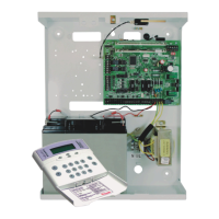
7.2 Mounting Procedure for the PCX system
The following steps illustrate basic mounting procedure for the PCX metal case.
Step 1 – Remove the case lid from the PCX panel and check all parts and components are in place.
Step 2 – Decide where the PCX panel will be situated. The PCX panel may be housed in the loft or different
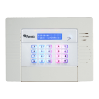
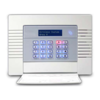
rooms in the premises. A discrete and concealed place is advisable, as only the PCX keypads need to be
seen.
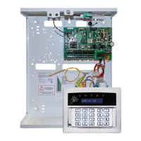
Step 3 – Secure the PCX panel to a sturdy and stable surface, using the mounting screws provided. First
mark the wall where the panel is to be situated (using the mounting holes), drill holes in the wall, and fasten
the panel base to the wall using the screws provided.
Step 4 – Before the panel base is completely secured to the wall feed cables for keypads / AC power supply
/ and accessories through the cable entry holes as illustrated.
7.3 Resistors
The resistor values are recognised as follows:
4k7 resistor = Yellow/Violet/Red
6k8 resistor = Blue/Grey/Red
470Ω resistor = Yellow/Violet/Brown
The PCX System recognises the following:
4k7: Alarm
4k7: Tamper
6k8: Mask/Fault (Not applicable on PCX 26/SMS)